Manuals
/
Bacharach
/
Household Appliance
/
Home Security System
Bacharach
2772-0803
manual
Remote Intelligent Sensor Area Monitor
Models:
2772-0803
1
26
49
49
Download
49 pages
53.56 Kb
23
24
25
26
27
28
29
30
Troubleshooting
Specifications
Install
System Alarms
Light Faults
Maintenance
Diagnostics
Internal BACK-UP Battery
Check and Adjust System
Battery Backup
Page 26
Image 26
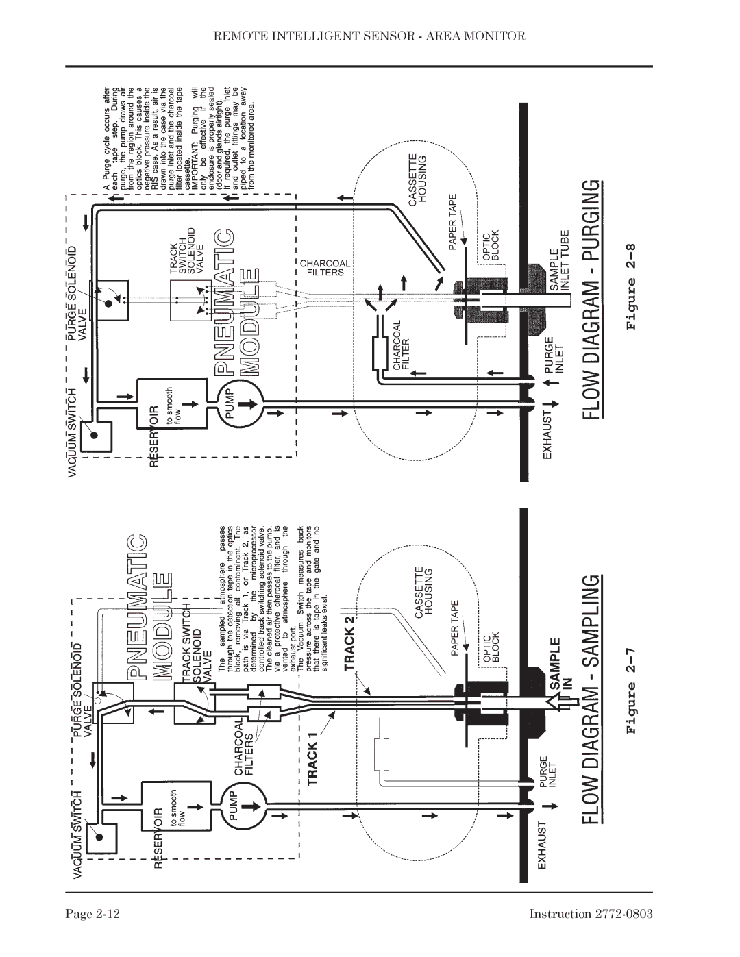
REMOTE INTELLIGENT SENSOR - AREA MONITOR
Figure
2-8
Figure
2-7
Page
2-12
Instruction
2772-0803
Page 25
Page 27
Page 26
Image 26
Page 25
Page 27
Contents
Instruction Remote Intelligent Sensor Area Monitor
Declaration of Conformity
Contents
Contents
Preparation Removal of the Mechanical Chassis
Verifying That a GAS Alarm WAS Caused by GAS
Cleaning the Sampling Input and Optics Block
Replacing the Mechanical Chassis
Monitored Concentration Levels High
A1.1 Adjusting Light Levels on Phase 1 RIS Units
RIS TEST/FAULT Parameter LOG Sheet
Supplement a
User Selectable Alarm SET Points
Continuous Diagnostics & System Test Mode
Battery Backup
Optional Features
Physical
Power Input Requirements
Accuracy
Outputs
Keyboard
Internal BACK-UP Battery
Display
Environmental
Table #1 RIS Catalog Numbers & Data
System Description
Basic Principles
Door Open and Cover Removed from Back of Door
Remote Intelligent Sensor Area Monitor
Remote Intelligent Sensor Area Monitor
Electrical Installation
Battery Connection
Mechanical Installation
Unpacking
System Power Supply Consideration & Selection
Specification
Sample Lines
RIS Type
Tools & Materials Required
1 Volt Conversion
System Check
Tape Cassette Loading
Check and Adjust System
For detailed instructions on adjustment
Interruption of Test Mode Cycle. If
Option PCB Installation
Without
Terminal USE
Silkscreen Idents NAL
Phase 2 Base Board Terminal Strips
Remote Intelligent Sensor Area Monitor
Remote Intelligent Sensor Area Monitor
Remote Intelligent Sensor Area Monitor
Complete Sampling Sequence
Twin Track Tape SAMPLING. At
Minimum Sample Time
CHANGE-OVER from Density to Time Mode
Density & Time Operating Modes
Tape Cassette Life
Flashing
System Alarms
Constant
Optics
Using the Keyboard
Diagnostics
Test Mode
Optional Features
Printer Operation & USE Optional Feature
Installing Test Card
Switch # 2 is not used and is left ‘ON
SW1 Total
White RED Prdy Black Pprs
Baud
OFF
Non-Bacharach Printer Interface
Data Busy Ground
Adjusting Light Levels
Maintenance General
Verifying That a GAS Alarm WAS Caused by GAS
Clearing a Spurious Alarm
Adjusting the Door Switch
Checking and Adjusting System Flow Rate
Disabling the ‘DOOR OPEN’ Alarm
Cleaning the Sampling Input and Optics Block
Measuring Pump Current
Cleaning Optics block
Stepping Clamp Vertical
Changing a Pump
Exterior Cleaning
KEY Parameter Checks
Mechanical Tightness
Input Path Cleaning
Troubleshooting General
Pump Check
Excessive Tape USE
Light Faults
Door Fault
Tape Breakage
Recommended Spares
System Power Supplies
Model Dependent Parts
Options and Supplies
Service Centers
Common Parts
Pennsylvania
200 to
Hold
Remote Intelligent Sensor Area Monitor
Instruction S-A3
S-A4 Instruction
Top
Page
Image
Contents