REMOTE INTELLIGENT SENSOR - AREA MONITOR
With the tape in place, adjust the track 1 potentiometer until the reading is 220. Clockwise rotation of potentiometers increases the level.
When track 1 has been adjusted, press the HOLD/RELEASE button to allow track 2 to be displayed. HOLD this display as before and adjust track 2 in the same manor as track 1.
After adjustments exit the TEST Mode by pressing the red button on the rear of the door again, unless other tests have to be done.
Exit the TEST Mode by pressing the red button on the rear of the door again, unless other tests have to be done.
4.5CHECKING AND ADJUSTING SYSTEM FLOW RATE
REFER to Table #1 to check the correct Flow Rate for your system.
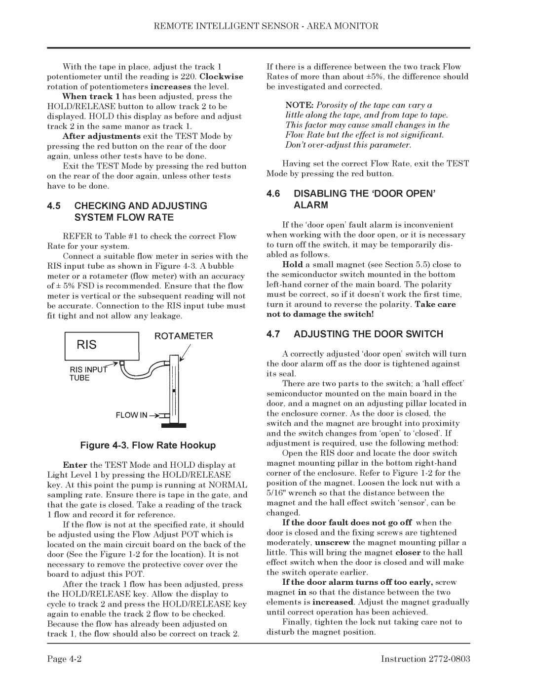
Connect a suitable flow meter in series with the RIS input tube as shown in Figure
Figure 4-3. Flow Rate Hookup
Enter the TEST Mode and HOLD display at Light Level 1 by pressing the HOLD/RELEASE key. At this point the pump is running at NORMAL sampling rate. Ensure there is tape in the gate, and that the gate is closed. Take a reading of the track 1 flow and record it for reference.
If the flow is not at the specified rate, it should be adjusted using the Flow Adjust POT which is located on the main circuit board on the back of the door (See the Figure
After the track 1 flow has been adjusted, press the HOLD/RELEASE key. Allow the display to cycle to track 2 and press the HOLD/RELEASE key again to enable the track 2 flow to be checked. Because the flow has already been adjusted on track 1, the flow should also be correct on track 2.
If there is a difference between the two track Flow Rates of more than about ±5%, the difference should be investigated and corrected.
NOTE: Porosity of the tape can vary a little along the tape, and from tape to tape. This factor may cause small changes in the Flow Rate but the effect is not significant. Don’t
Having set the correct Flow Rate, exit the TEST Mode by pressing the red button.
4.6DISABLING THE ‘DOOR OPEN’ ALARM
If the ‘door open’ fault alarm is inconvenient when working with the door open, or it is necessary to turn off the switch, it may be temporarily dis- abled as follows.
Hold a small magnet (see Section 5.5) close to the semiconductor switch mounted in the bottom
4.7ADJUSTING THE DOOR SWITCH
A correctly adjusted ‘door open’ switch will turn the door alarm off as the door is tightened against its seal.
There are two parts to the switch; a ‘hall effect’ semiconductor mounted on the main board in the door, and a magnet on an adjusting pillar located in the enclosure corner. As the door is closed, the switch and the magnet are brought into proximity and the switch changes from ‘open’ to ‘closed’. If adjustment is required, use the following method:
Open the RIS door and locate the door switch magnet mounting pillar in the bottom
If the door fault does not go off when the door is closed and the fixing screws are tightened moderately, unscrew the magnet mounting pillar a little. This will bring the magnet closer to the hall effect switch when the door is closed and will make the switch operate earlier.
If the door alarm turns off too early, screw magnet in so that the distance between the two elements is increased. Adjust the magnet gradually until correct operation has been achieved.
Finally, tighten the lock nut taking care not to disturb the magnet position.
Page | Instruction |