________________________________________________________________________
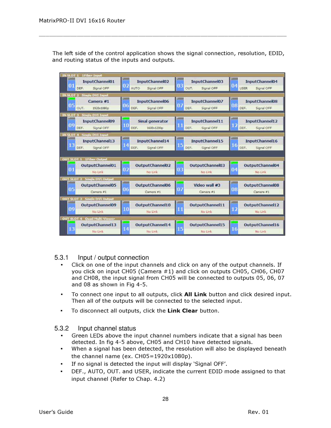
The left side of the control application shows the signal connection, resolution, EDID, and routing status of the inputs and outputs.
5.3.1Input / output connection
▪Click on one of the input channels and click on any of the output channels. If you click on input CH05 (Camera #1) and click on outputs CH05, CH06, CH07 and CH08, the input signal from CH05 will be connected to outputs 05, 06, 07 and 08 as shown in Fig
▪To connect one input to all outputs, click All Link button and click desired input. Then all of the outputs will be connected to the selected input.
▪To disconnect all outputs, click the Link Clear button.
5.3.2Input channel status
▪Green LEDs above the input channel numbers indicate that a signal has been detected. In fig
▪When a signal has been detected, the resolution will also be displayed beneath the channel name (ex. CH05=1920x1080p).
▪If no signal is detected the input will display ‘Signal OFF’.
▪DEF., AUTO, OUT. and USER, indicate the current EDID mode assigned to that input channel (Refer to Chap. 4.2)
28
User’s Guide | Rev. 01 |