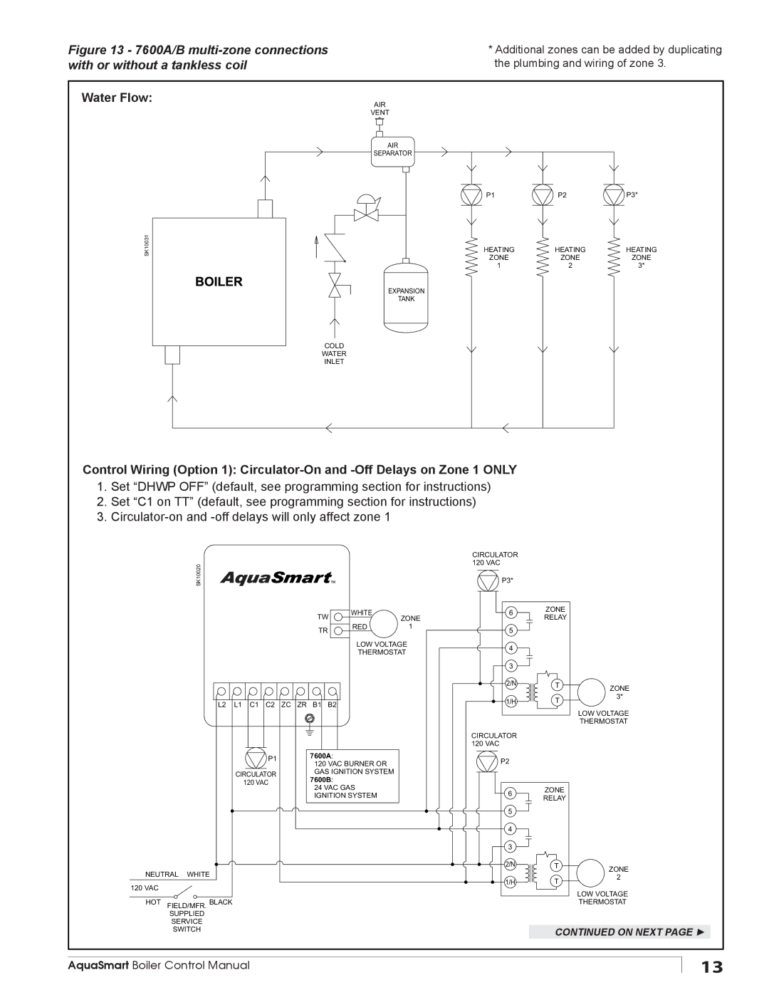
Figure 13 - 7600A/B | * Additional zones can be added by duplicating |
with or without a tankless coil | the plumbing and wiring of zone 3. |
Water Flow:
AIR
VENT
AIR
SEPARATOR
SK10031
EXPANSION
TANK
COLD
WATER
INLET
P1 | P2 | P3* |
HEATING | HEATING | HEATING |
ZONE | ZONE | ZONE |
1 | 2 | 3* |
Control Wiring (Option 1):
1.Set “DHWP OFF” (default, see programming section for instructions)
2.Set “C1 on TT” (default, see programming section for instructions)
3.
SK10020
TW | WHITE | ZONE |
| ||
TR | RED | 1 |
|
|
LOW VOLTAGE
THERMOSTAT
L2 L1 C1 C2 ZC ZR B1 B2
P1 | 7600A: | |
120 VAC BURNER OR | ||
| ||
CIRCULATOR | GAS IGNITION SYSTEM | |
7600B: | ||
120 VAC |
24 VAC GAS IGNITION SYSTEM
NEUTRAL WHITE
120 VAC
HOT FIELD/MFR. BLACK
SUPPLIED
SERVICE
SWITCH
CIRCULATOR |
|
|
120 VAC |
|
|
P3* |
|
|
6 | ZONE |
|
RELAY |
| |
|
| |
5 |
|
|
4 |
|
|
3 |
|
|
2/N | T | ZONE |
|
| |
1/H | T | 3* |
| ||
|
| LOW VOLTAGE |
|
| THERMOSTAT |
CIRCULATOR |
|
|
120 VAC |
|
|
P2 |
|
|
6 | ZONE |
|
RELAY |
| |
|
| |
5 |
|
|
4 |
|
|
3 |
|
|
2/N | T | ZONE |
|
| |
1/H | T | 2 |
| ||
|
| LOW VOLTAGE |
|
| THERMOSTAT |
CONTINUED ON NEXT PAGE ►
AquaSmart Boiler Control Manual
13
