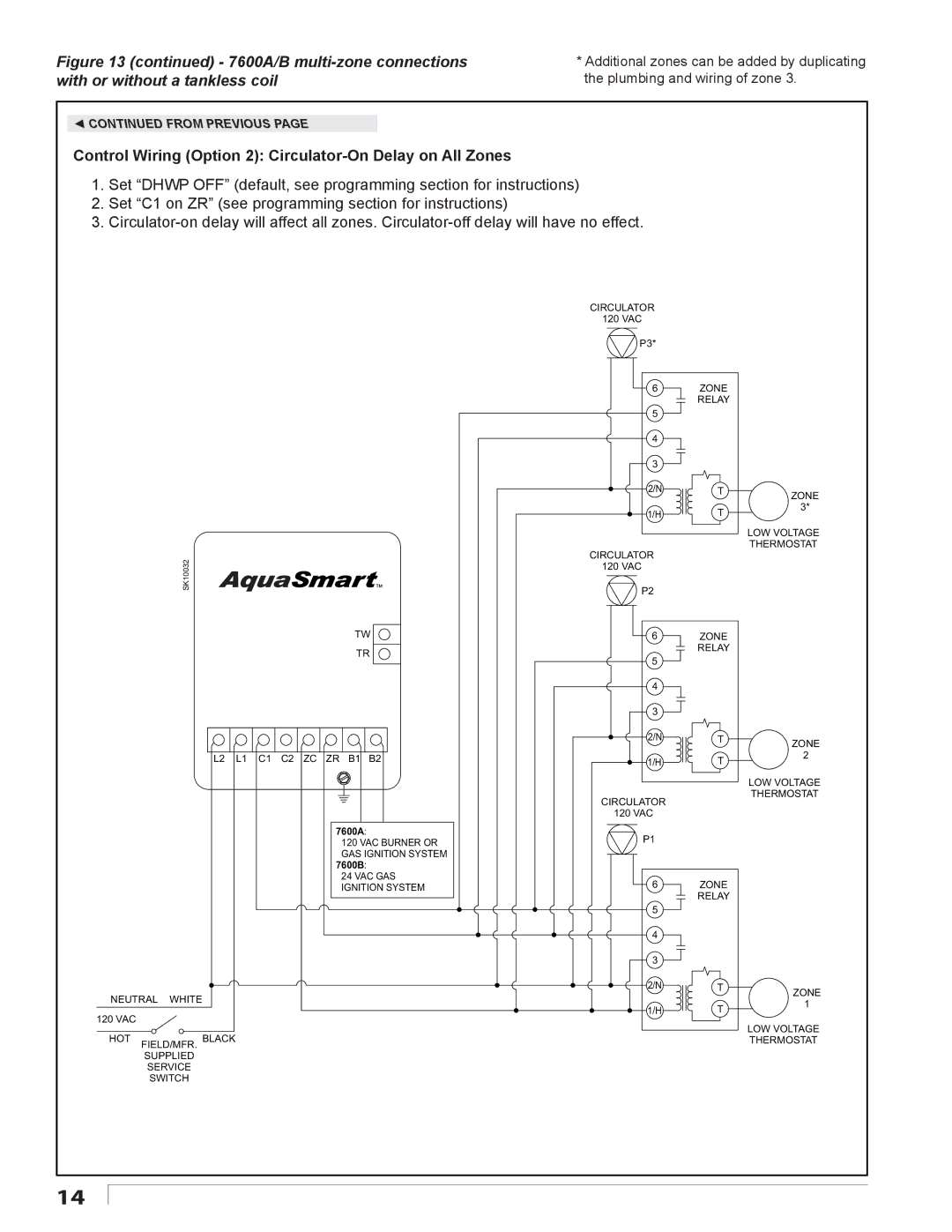
Figure 13 (continued) - 7600A/B multi-zone connections with or without a tankless coil
*Additional zones can be added by duplicating the plumbing and wiring of zone 3.
◄CONTINUED FROM PREVIOUS PAGE
Control Wiring (Option 2): Circulator-On Delay on All Zones
1.Set “DHWP OFF” (default, see programming section for instructions)
2.Set “C1 on ZR” (see programming section for instructions)
3.
SK10032
TW
TR
L2 L1 C1 C2 ZC ZR B1 B2
7600A:
120 VAC BURNER OR GAS IGNITION SYSTEM
7600B:
24 VAC GAS IGNITION SYSTEM
NEUTRAL WHITE
120 VAC
HOT FIELD/MFR. BLACK
SUPPLIED
SERVICE
SWITCH
CIRCULATOR
120VAC P3*
6ZONE RELAY
5
4
3
2/N T
1/H T
CIRCULATOR
120VAC P2
6ZONE RELAY
5
4
3
2/N T
1/H T
CIRCULATOR
120VAC
P1
6ZONE RELAY
5
4
3
2/N T
1/H T
ZONE
3*
LOW VOLTAGE THERMOSTAT
ZONE
2
LOW VOLTAGE THERMOSTAT
ZONE
1
LOW VOLTAGE THERMOSTAT
14
