20V MAx* Li-ion 5-1/2inch 140mm Circular saw
Catalog Number
Safety Guidelines Definitions
Work Area Safety
Save all warnings and instructions for future reference
Safety instructionS for all saws
Service
Causes and operator Prevention of kickback
Wire Size AWG
75 ft 100 ft 125 ft
175 ft
25 ft 50 ft
Amperes
Volts
Revolutions or reciprocations
Double insulated Per minute
Important safety instructions for battery chargers
Charging Procedure
Charge the battery packs only in Black and Decker chargers
Read all Instructions
Storage Recommendations
Charger Diagnostics
Bad battery
Hot/Cold pack delay
Leaving the battery in the charger
Assembly/Adjustment Set-Up
Lithium Ion Battery Pack and Charger Description Catalog #
Intended Use
Installing and Removing the Battery Pack From the Tool
Supporting Large Panels / Securing Workpiece
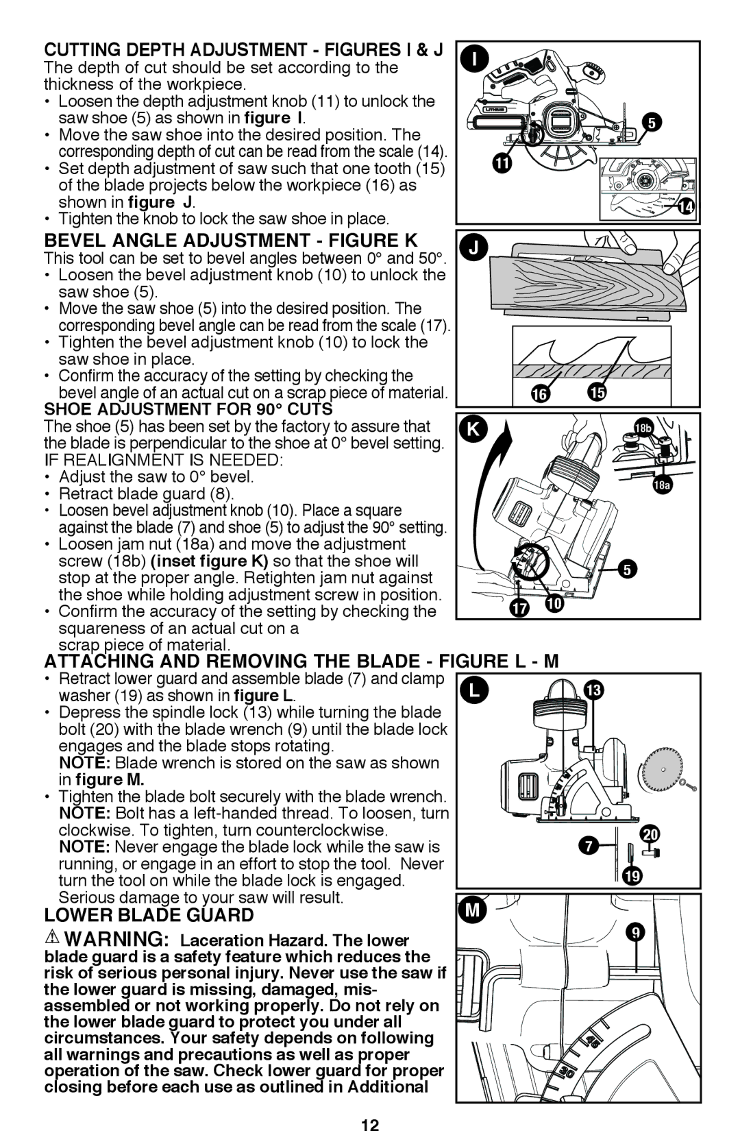
Cutting Depth Adjustment Figures I & J
Bevel Angle Adjustment Figure K
Shoe Adjustment For 90 Cuts
Attaching and Removing the Blade figure L M
Operating Instructions
Troubleshooting
Accessories
Problem Possible Solution Possible Cause
Maximize the life
Limited Two-Year Home Use Warranty
Battery
Sercive information
Scie circulaire de Li-ion de 20 V max.*, 140 mm 5 1/2 po
Numero de catalogue
Lignes directrices en matière de sécurité définitions
Page
Page
Calibre de fil minimum recommandé pour les rallonges
Directives de sécurité supplémentaires
Longueur totale de la rallonge
Calibre AWG
Symboles
Mis à la terre Symbole d´avertissement
· le plomb dans les peintures à base de plomb
Pour Réduire LE Risque D’EFFET DE Rebond
Garder les lames aiguisées et propres
Utilisation Prévue
Avertissement
Conserver CES Directives
Directives de sécurité importantes pour les blocs-piles
Lire toutes les directives
Recommandations en matière de rangement
Fixation murale
Procédure de charge
Fonctions de diagnostic du chargeur
Pile en mauvais état
Fonction de suspension du bloc-piles chaud/froid
Bloc-piles laissé dans le chargeur
CLÉ
Bloc-piles au lithium-ion de 20 V max
Chargeur rapide de 2A LCS1620
Installer des pièces d’appui sous le panneau, des
Insertion et retrait du bloc-piles de l’outil
Soutien de grands panneaux/fixation de la pièce
Deux cotés, près de la ligne de coupe et du bord du
Réglage de la profondeur de coupe
Réglage de l’angle de biseau figure K
Réglage de la semelle pour les coupes
Fixation et retrait de la lame figure L M
Fonctionnement
Coupes Générales
Détente
Problème Dépannage Solution possible Cause possible
Découpe EN Poche Figure N
Frein électrique automatique
Sciage
Accessoires
Entretien
Le sceau Rbrcmc
Remarques spéciales sur l’emploi avec des piles au lithium
Page
Sierra circular de 140 mm
Catálogo N
Pautas DE SEGURIDAD/DEFINICIONES
Page
Peligro
Mantenimiento
Esto garantizará la seguridad de la herramienta eléctrica
Instrucciones de seguridad adicionales
Pies
Tamaño AWG del conductor
Para Reducir EL Riesgo DE Retroceso
Símbolos
Voltios Amperios Hertz Vatios
Minutos Corriente alterna Corriente directa
Advertencia
Conserve Estas Instrucciones
Lea todas las instrucciones
Montaje en la pared
Procedimiento de carga
Batería en mal estado
Retraso por paquete caliente/frío
Figura a
Escala de ajuste de profundidad no SE Muestra
Uso previsto
Descripción De cat
Advertencia Para reducir el riesgo de lesiones, siempre
Soporte de paneles grandes/Fijación de
Ensamblado/Regulaciones
Ajuste de la profundidad de corte
Regulación del ángulo de bisel
Ajuste de la zapata para cortes de
Instrucciones de operación
Protector inferior de la hoja
Colocación y remoción de la hoja Fig. L, M
En la figura L
Cortes Internos FIGURA N
Cortes Generales
Interruptor
Freno Eléctrico Automático
Notas especiales para el uso con baterías de litio
Maximizar la vida útil del
Paquete de baterías, este
Mantenimiento
El sello Rbrc
Page
Telephone · No. Teléfono
Años DE Garantia
Esta Garantia no Aplica Cuando
Solamente Para Propositos DE Mexico
20V MAX* Cordless Drill
Catalog Number
General Power Tool Safety Warnings
Save all warnings and instructions for future reference
Page
Always Wear Certified Safety Equipment
Volts Hertz Watts
Important Safety Instructions for Battery
Functional Description
Chargers
Importantsafety Instruction for Batterypacks
Read ALL Instructions
Summer
Recycling
Pattern indicated on the label
Safety Warnings and Instructions Drills
Installing and Removing the Battery Pack from the Tool
Trigger Switch & Reversing Button Figure D
Before installing or removing accessories
Operating Instructions
Torque Control Figure E
Dual Range Gearing Figure G
Screw Driving
On Board BIT Storage Figure H
Drilling
Troubleshooting
Maintenance
Drilling in Metal
Drilling in Masonry
Service Information Full TWO-YEAR Home USE Warranty
Mode DʼEMPLOI DE LA Perceuse Sans FIL DE 16V MAX*, 20V MAX
Page
Deélectriquelʼoutil électrique
Contrôler
Ins médicaux Le liquide qui gicle
Utilisation sécuritaire de lʼoutil électrique
Exposition au bruit peut entraîner une perte auditive
Peut entraîner des blessures corporelles
Tours à la minute
Détente de vitesse variable
Bague de réglage du couple Mandrin auto-serrant
Chargeurs DE Piles
Risques de choc électrique, dʼélectrocution ou dʼincendie
Manuels fournis avec lʼoutil avant dʼutiliser le chargeur
Consignes de chargement décrites
Sont dégagées lorsque les blocs-piles sont incinérés
Recommandations EN Matière DE Rangement
Fonctions DE Diagnostic DU Chargeur
Procédure DE Charge
Pile EN Mauvais État
Ne jamais ouvrir le bloc-piles pour
Insertion ET Retrait DU BLOC-PILES DE LʼOUTIL
Insertion DU BLOC-PILES Insérer le bloc-piles
Retrait DU BLOC-PILES Enfoncer le bouton de
Détente ET Bouton Inverseur Figure D
Réglage DU Couple Figure E
Serrer la première vis
Mandrin Sans CLÉ Figure F
Vissage
Rangement Intégré DES Mèches Figure H
Perçage
Perçage DU Bois
LE Sceau Rbrcmc
Perçage DE LA Maçonnerie
Problème
Dépannage
Information SUR LES Réparations
Manual DE Instrucciones DEL Taladro Inalámbrico DE 20V MÁX
Seguridad eléctrica
Mantenimiento adecuado.Las herramientas de
Uso y mantenimiento de la herramienta con baterías
Quemadurasterminal al otroo incendio
Garantizará la seguridad de la herramienta eléctrica
Puede ocasionar la pérdida de la audición
Control podría ocasionar lesiones personales
Terminales de conexión a tierre
Símbolo de alerta
LEA Todas LAS Instrucciones
Electrocución
Pies
De la cubierta
Cargue los paquetes de baterías sólo con cargadoresde
Recomendaciones CON Respecto AL Almacenamiento
Procedimiento DE Carga
Diagnóstico DEL Cargador
Batería EN MAL Estado
Retraso POR Paquete CALIENTE/FRÍO
Dejar LA Batería EN EL Cargador
Instrucciones DE Operación
Para Instalar EL Paquete DE Baterías
Para Extraer EL Paquete DE Baterías
Interruptor Disparador Y Botón DE Inversión Figura D
Ajuste DEL Control DE Torsión Figura E
Portabrocas SIN Llave Figura F
Advertencia Asegúrese de que el botón
Accesorios
Destornillado
Espacio EN LA Herramienta Para Guardar Brocas Figura H
Taladrado
Taladrado EN Madera
Problema
Detección DE Problemas
Maximizarlavidaútildel
Ayuda Black & Decker al 01 800 847 2309/01 800 847
Page
Product Infomation · Identificación DEL Producto
Para Servicio y ventas
20v max* reciprocating saw
Page
Safety Guidelines Definitions
Specific Safety Rules
Use power tools only with
Important Safety Instructions for Battery Chargers
Lead from lead-based paints
Arsenic and chromium from chemically-treated lumber
Double insulated
Important Safety Instruction for Battery Packs
Charge the battery packs only in Black & Decker chargers
Charging Procedure
Leaving the battery
Important charging notes
FUNCTIONAL DESCRIPTION Figure a
Trigger Switch
Place blade and shoe firmly against work to be cut
Insert blade shank from the front
For cutting aluminum, kerosene is preferred
Troubleshooting
Maintenance
Accessories
PROJECT TIPS
Service Information Limited Two-Year Home Use Warranty
Latin America This warranty
Rbrc Seal
Free warning label
Scie alternative de 20 V MAX
Page
Consignes de sécurité particulières
Avertissement Toujours
Avertissement
Avertissement certains
Conserver CES Directives
Avertissement pour un
D. un dessus de table ou d’établi
Recommandations en matière de rangement
Avertissement ne jamais
Avertissement risque
Procédure de charge
Fonctionnement Avertissement toujours
Détente
Conseils Pour LES Projets
Problème Cause possible Solution possible
Dépannage
Lubrification
Bloc-piles, celui-ci est conçu Pour s’éteindre soudainement
Accessoires Avertissement L’utilisation
Entretien
Le sceau Rbrc
Information sur les réparations
Pautas DE SEGURIDAD/DEFINICIONES
Conserve este manual para futuras consultas
Chispas que pueden encender el polvo o los vapores
Seguridad personal
Muchos accidentes a causa de las
Provocar que las partes metálicas
Expuestas de la herramienta eléctrica
Propensas a trabarse y son más
Advertencia El uso de esta
Advertencia Riesgo de
Precaución Riesgo de
Advertencia Para un
Advertencia Peligro de
Advertencia Nunca intente
Tensiones de alguna otra forma
Procedimiento de carga
Notas importantes sobre la carga
Palanca de liberación de la abrazadera de la hoja
Instalación Y Extracción DEL Paquete DE Baterías
Advertencia Utilice siempre la
Además de daños en la zapata y en la pieza de trabajo
Sugerencias Para EL Proyecto
Lubricación
Detección de problemas
Mantenimiento
Accesorios
Advertencia El uso de
El sello Rbrc
América Latina esta garantía no
El sello Rbrc Corporación
Años DE Garantia
Tel 88 95