ADJUSTING THE BELT TENSION
Your sander was shipped from the factory with the drive belt (A) Fig. 1 attached to both pulleys (B) and (C). Before assembling the machine, check and adjust the belt tension.
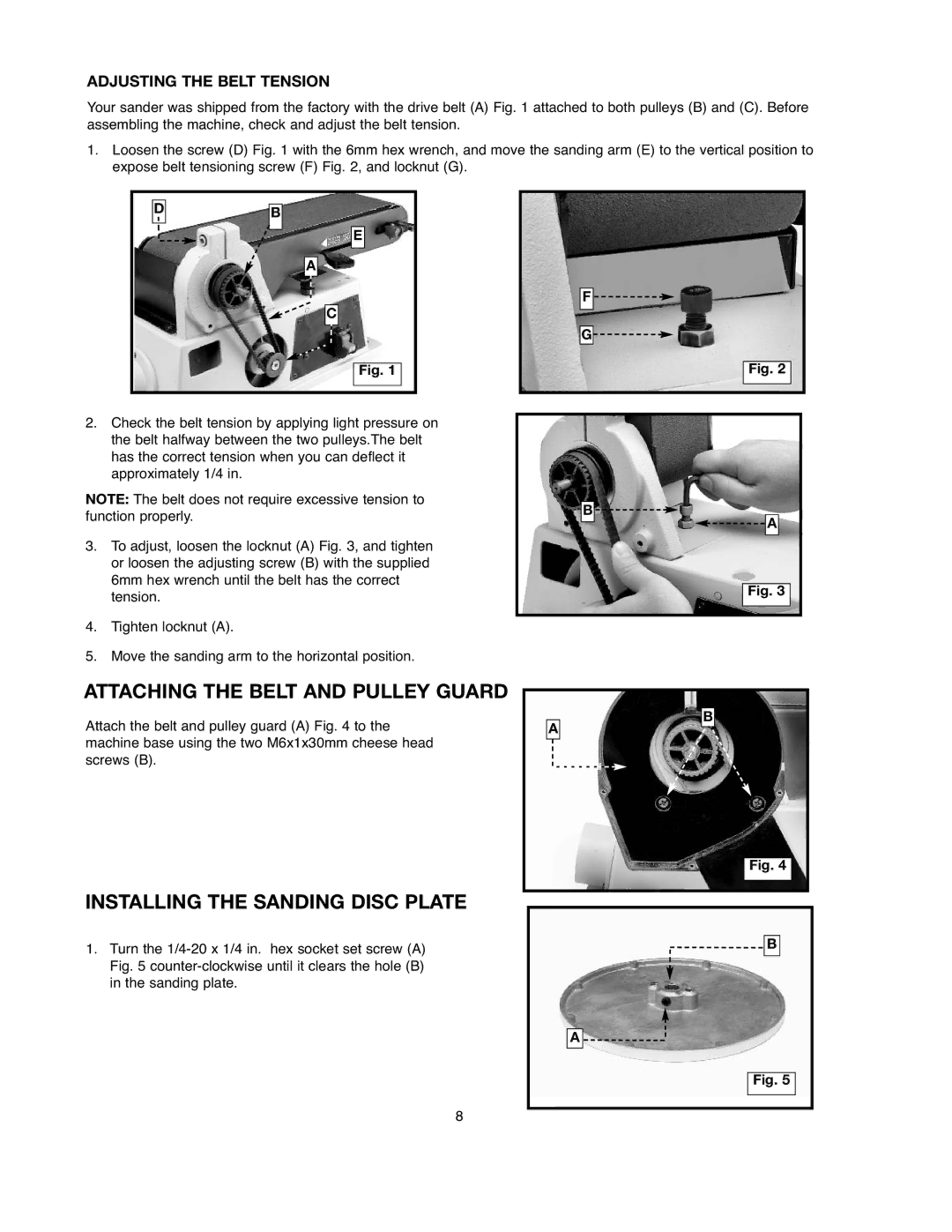
1.Loosen the screw (D) Fig. 1 with the 6mm hex wrench, and move the sanding arm (E) to the vertical position to expose belt tensioning screw (F) Fig. 2, and locknut (G).
D
B
E
A
C
Fig. 1
F![]()
![]()
![]()
G![]()
Fig. 2
2.Check the belt tension by applying light pressure on the belt halfway between the two pulleys.The belt has the correct tension when you can deflect it approximately 1/4 in.
NOTE: The belt does not require excessive tension to function properly.
3.To adjust, loosen the locknut (A) Fig. 3, and tighten or loosen the adjusting screw (B) with the supplied 6mm hex wrench until the belt has the correct tension.
4.Tighten locknut (A).
5.Move the sanding arm to the horizontal position.
ATTACHING THE BELT AND PULLEY GUARD
Attach the belt and pulley guard (A) Fig. 4 to the machine base using the two M6x1x30mm cheese head screws (B).
INSTALLING THE SANDING DISC PLATE
1.Turn the
B![]()
![]()
![]()
![]() A
A
Fig. 3
B
A
Fig. 4
![]() B
B
A ![]()
Fig. 5
8