ADJUSTING THE MITER GAUGE SLOT PARALLEL WITH THE SANDING DISC
![]() WARNING: DISCONNECT MACHINE FROM POWER SOURCE.
WARNING: DISCONNECT MACHINE FROM POWER SOURCE.
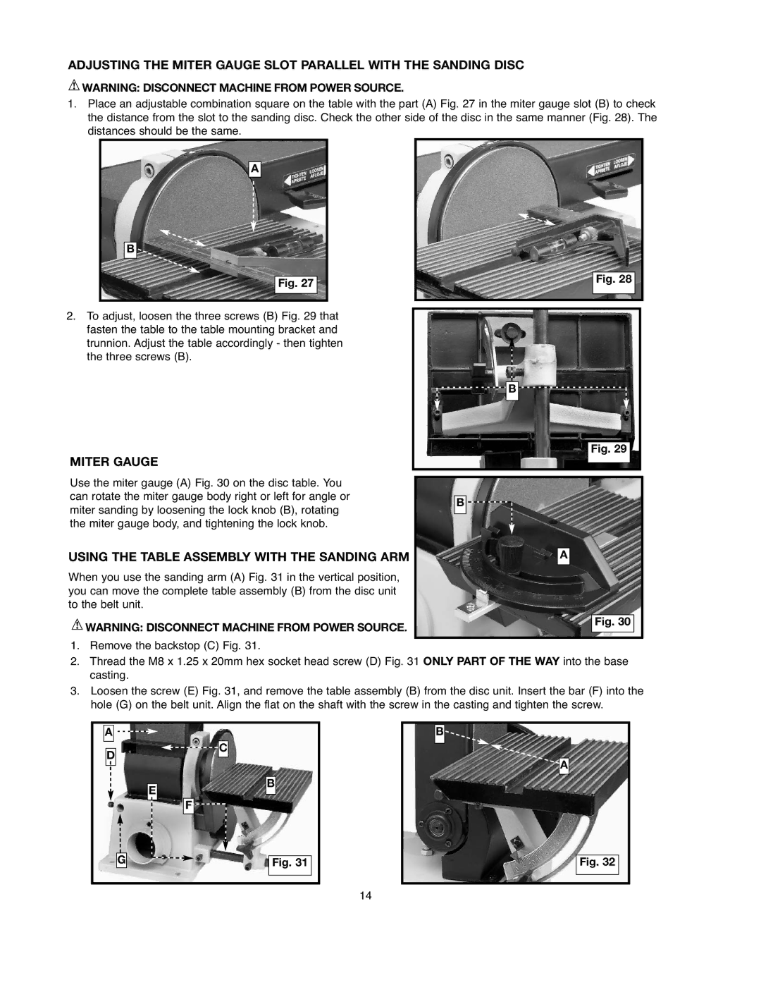
1.Place an adjustable combination square on the table with the part (A) Fig. 27 in the miter gauge slot (B) to check the distance from the slot to the sanding disc. Check the other side of the disc in the same manner (Fig. 28). The distances should be the same.
A
B ![]()
Fig. 27
Fig. 28
2.To adjust, loosen the three screws (B) Fig. 29 that fasten the table to the table mounting bracket and trunnion. Adjust the table accordingly - then tighten the three screws (B).
MITER GAUGE
Use the miter gauge (A) Fig. 30 on the disc table. You can rotate the miter gauge body right or left for angle or miter sanding by loosening the lock knob (B), rotating the miter gauge body, and tightening the lock knob.
USING THE TABLE ASSEMBLY WITH THE SANDING ARM
When you use the sanding arm (A) Fig. 31 in the vertical position, you can move the complete table assembly (B) from the disc unit to the belt unit.
![]() WARNING: DISCONNECT MACHINE FROM POWER SOURCE.
WARNING: DISCONNECT MACHINE FROM POWER SOURCE.
B |
Fig. 29 |
B |
A |
Fig. 30
1.Remove the backstop (C) Fig. 31.
2.Thread the M8 x 1.25 x 20mm hex socket head screw (D) Fig. 31 ONLY PART OF THE WAY into the base casting.
3.Loosen the screw (E) Fig. 31, and remove the table assembly (B) from the disc unit. Insert the bar (F) into the hole (G) on the belt unit. Align the flat on the shaft with the screw in the casting and tighten the screw.
A![]()
![]()
![]()
B |
D
C
E
F ![]()
![]()
G
B
Fig. 31
A |
Fig. 32 |
14