ADJUSTING THE LOWER BLADE GUARD
DISCONNECT THE MACHINE FROM
POWER SOURCE.
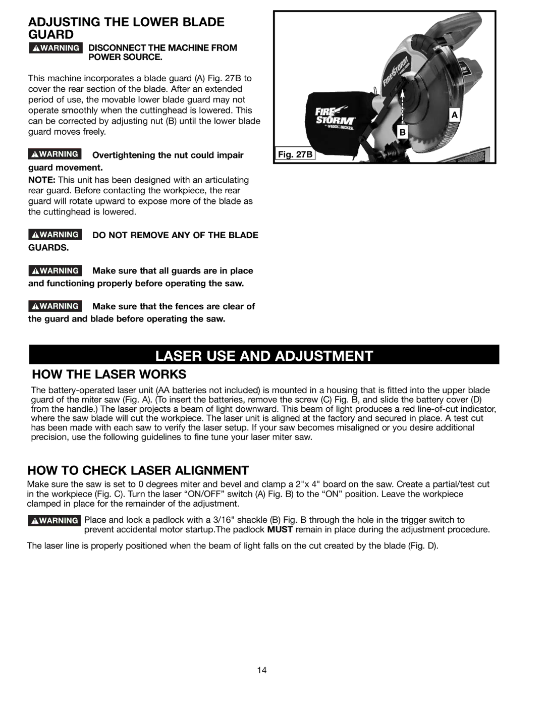
This machine incorporates a blade guard (A) Fig. 27B to cover the rear section of the blade. After an extended period of use, the movable lower blade guard may not operate smoothly when the cuttinghead is lowered. This can be corrected by adjusting nut (B) until the lower blade guard moves freely.
![]() Overtightening the nut could impair guard movement.
Overtightening the nut could impair guard movement.
NOTE: This unit has been designed with an articulating rear guard. Before contacting the workpiece, the rear guard will rotate upward to expose more of the blade as the cuttinghead is lowered.
 DO NOT REMOVE ANY OF THE BLADE GUARDS.
Fig. 27B
A
B
![]() Make sure that all guards are in place and functioning properly before operating the saw.
Make sure that all guards are in place and functioning properly before operating the saw.
![]() Make sure that the fences are clear of the guard and blade before operating the saw.
Make sure that the fences are clear of the guard and blade before operating the saw.
LASER USE AND ADJUSTMENT
HOW THE LASER WORKS
The
HOW TO CHECK LASER ALIGNMENT
Make sure the saw is set to 0 degrees miter and bevel and clamp a 2"x 4" board on the saw. Create a partial/test cut in the workpiece (Fig. C). Turn the laser “ON/OFF” switch (A) Fig. B) to the “ON” position. Leave the workpiece clamped in place for the remainder of the adjustment.
![]() Place and lock a padlock with a 3/16" shackle (B) Fig. B through the hole in the trigger switch to prevent accidental motor startup.The padlock MUST remain in place during the adjustment procedure.
Place and lock a padlock with a 3/16" shackle (B) Fig. B through the hole in the trigger switch to prevent accidental motor startup.The padlock MUST remain in place during the adjustment procedure.
The laser line is properly positioned when the beam of light falls on the cut created by the blade (Fig. D).
14