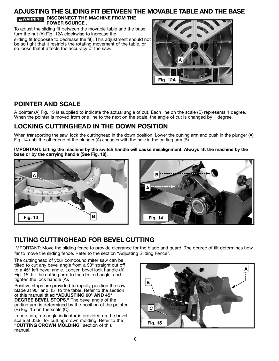
ADJUSTING THE SLIDING FIT BETWEEN THE MOVABLE TABLE AND THE BASE
DISCONNECT THE MACHINE FROM THE
POWER SOURCE .
To adjust the sliding fit between the movable table and the base, turn the nut (A) Fig. 12A clockwise to increase the
sliding fit (opposite to decrease the fit). This adjustment should not be so tight that it restricts the rotating movement of the table, or so loose that it affects the accuracy of the saw.
A
Fig. 12A
POINTER AND SCALE
A pointer (A) Fig. 13 is supplied to indicate the actual angle of cut. Each line on the scale (B) represents 1 degree. When the pointer is moved from one line to the next on the scale, the angle of cut is changed by 1 degree.
LOCKING CUTTINGHEAD IN THE DOWN POSITION
When transporting the saw, lock the cuttinghead in the down position. Lower the cutting arm and push in the plunger (A) Fig. 14 until the other end of the plunger (A) engages with the hole in the cutting arm (B).
IMPORTANT: Lifting the machine by the switch handle will cause misalignment. Always lift the machine by the base or by the carrying handle (See Fig. 18).
A
B![]()
![]()
![]()
A ![]()
![]()
![]()
Fig. 13
B
Fig. 14
TILTING CUTTINGHEAD FOR BEVEL CUTTING
IMPORTANT: Move the sliding fence to provide clearance for the blade and guard. The degree of tilt determines how far to move the sliding fence. Refer to the section “Adjusting Sliding Fence”.
The cuttinghead of your compound miter saw can be tilted to cut any bevel angle from a 90° straight cut off to a 45° left bevel angle. Loosen bevel lock handle (A) Fig. 15, tilt the cutting arm to the desired angle, and tighten the lock handle (A).
Positive stops are provided to rapidly position the saw blade at 90° and 45° to the table. Refer to the section of this manual titled “ADJUSTING 90° AND 45° DEGREE BEVEL STOPS.” The bevel angle of the cutting arm is determined by the position of the pointer
(B) Fig. 15 on the scale (C).
In addition, a triangle indicator is provided on the bevel scale at 33.9° for cutting crown molding. Refer to the “CUTTING CROWN MOLDING” section of this manual.
B
C
Fig. 15
A
10