256-KBPS LINE DRIVER (V.35, RS-530, OR X.21)
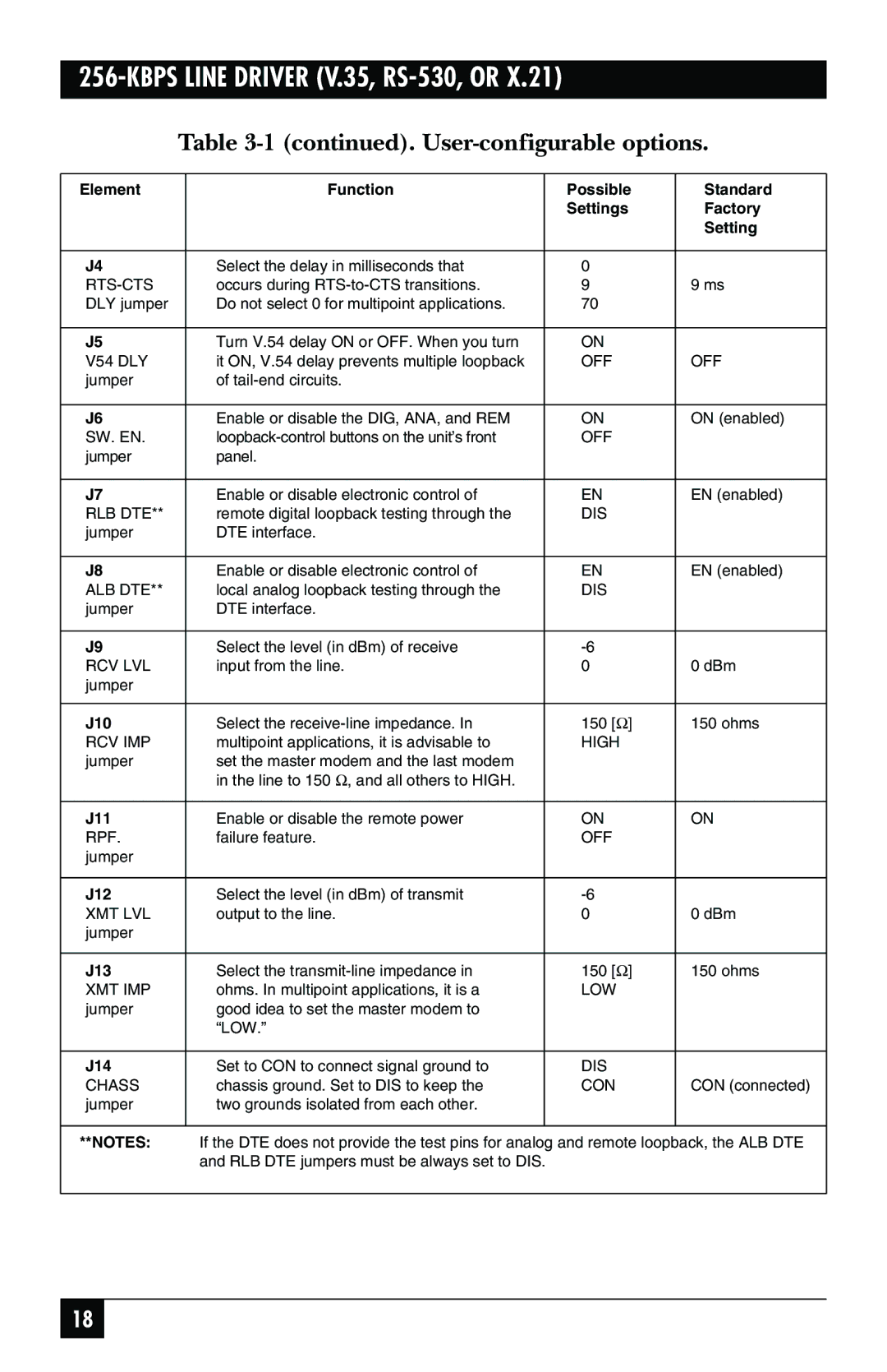
Table 3-1 (continued). User-configurable options.
Element | Function |
| Possible | Standard |
|
|
| Settings | Factory |
|
|
|
| Setting |
|
|
|
|
|
J4 | Select the delay in milliseconds that |
| 0 |
|
| occurs during |
| 9 | 9 ms |
DLY jumper | Do not select 0 for multipoint applications. |
| 70 |
|
|
|
|
|
|
J5 | Turn V.54 delay ON or OFF. When you turn |
| ON |
|
V54 DLY | it ON, V.54 delay prevents multiple loopback |
| OFF | OFF |
jumper | of |
|
|
|
|
|
|
|
|
J6 | Enable or disable the DIG, ANA, and REM |
| ON | ON (enabled) |
SW. EN. |
| OFF |
| |
jumper | panel. |
|
|
|
|
|
|
|
|
J7 | Enable or disable electronic control of |
| EN | EN (enabled) |
RLB DTE** | remote digital loopback testing through the |
| DIS |
|
jumper | DTE interface. |
|
|
|
|
|
|
|
|
J8 | Enable or disable electronic control of |
| EN | EN (enabled) |
ALB DTE** | local analog loopback testing through the |
| DIS |
|
jumper | DTE interface. |
|
|
|
|
|
|
|
|
J9 | Select the level (in dBm) of receive |
|
| |
RCV LVL | input from the line. |
| 0 | 0 dBm |
jumper |
|
|
|
|
|
|
|
|
|
J10 | Select the |
| 150 [Ω] | 150 ohms |
RCV IMP | multipoint applications, it is advisable to |
| HIGH |
|
jumper | set the master modem and the last modem |
|
|
|
| in the line to 150 Ω, and all others to HIGH. |
|
|
|
|
|
|
|
|
J11 | Enable or disable the remote power |
| ON | ON |
RPF. | failure feature. |
| OFF |
|
jumper |
|
|
|
|
|
|
|
|
|
J12 | Select the level (in dBm) of transmit |
|
| |
XMT LVL | output to the line. |
| 0 | 0 dBm |
jumper |
|
|
|
|
|
|
|
|
|
J13 | Select the |
| 150 [Ω] | 150 ohms |
XMT IMP | ohms. In multipoint applications, it is a |
| LOW |
|
jumper | good idea to set the master modem to |
|
|
|
| “LOW.” |
|
|
|
|
|
|
|
|
J14 | Set to CON to connect signal ground to |
| DIS |
|
CHASS | chassis ground. Set to DIS to keep the |
| CON | CON (connected) |
jumper | two grounds isolated from each other. |
|
|
|
|
|
|
| |
**NOTES: | If the DTE does not provide the test pins for analog and remote loopback, the ALB DTE | |||
| and RLB DTE jumpers must be always set to DIS. |
|
| |
|
|
|
|
|
18