CHAPTER 4: Installation
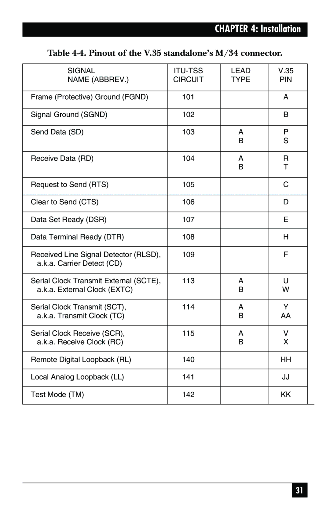
Table 4-4. Pinout of the V.35 standalone’s M/34 connector.
SIGNAL |
| LEAD | V.35 |
|
NAME (ABBREV.) | CIRCUIT | TYPE | PIN |
|
|
|
|
|
|
Frame (Protective) Ground (FGND) | 101 |
| A |
|
|
|
|
|
|
Signal Ground (SGND) | 102 |
| B |
|
|
|
|
|
|
Send Data (SD) | 103 | A | P |
|
|
| B | S |
|
|
|
|
|
|
Receive Data (RD) | 104 | A | R |
|
|
| B | T |
|
|
|
|
|
|
Request to Send (RTS) | 105 |
| C |
|
|
|
|
|
|
Clear to Send (CTS) | 106 |
| D |
|
|
|
|
|
|
Data Set Ready (DSR) | 107 |
| E |
|
|
|
|
|
|
Data Terminal Ready (DTR) | 108 |
| H |
|
|
|
|
|
|
Received Line Signal Detector (RLSD), | 109 |
| F |
|
a.k.a. Carrier Detect (CD) |
|
|
|
|
|
|
|
|
|
Serial Clock Transmit External (SCTE), | 113 | A | U |
|
a.k.a. External Clock (EXTC) |
| B | W |
|
|
|
|
|
|
Serial Clock Transmit (SCT), | 114 | A | Y |
|
a.k.a. Transmit Clock (TC) |
| B | AA |
|
|
|
|
|
|
Serial Clock Receive (SCR), | 115 | A | V |
|
a.k.a. Receive Clock (RC) |
| B | X |
|
|
|
|
|
|
Remote Digital Loopback (RL) | 140 |
| HH |
|
|
|
|
|
|
Local Analog Loopback (LL) | 141 |
| JJ |
|
|
|
|
|
|
Test Mode (TM) | 142 |
| KK |
|
|
|
|
|
|
31