Black Box ME444AE-530-R3, ME444AE-R3, ME445C-35 Functional Description, Line driver block diagram

Models: ME445C-530 ME444A-530-R3 ME444A-R3 ME444AE-530-R3 ME445C-35 ME445C-X.21 ME444AE-R3

1 49
Download 49 pages 34.86 Kb
Page 12
Image 12

CHAPTER 2: Introduction

2.2 Functional Description

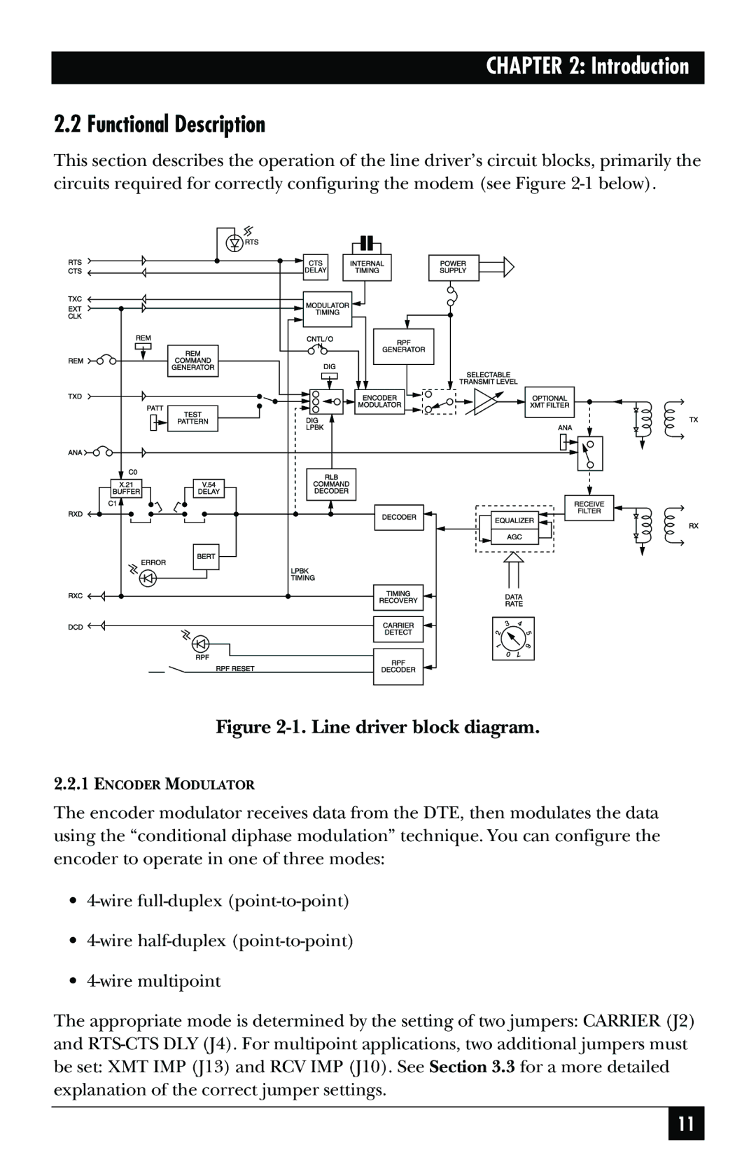
This section describes the operation of the line driver’s circuit blocks, primarily the circuits required for correctly configuring the modem (see Figure 2-1 below).

Figure 2-1. Line driver block diagram.

2.2.1ENCODER MODULATOR

The encoder modulator receives data from the DTE, then modulates the data using the “conditional diphase modulation” technique. You can configure the encoder to operate in one of three modes:

4-wire full-duplex (point-to-point)

4-wire half-duplex (point-to-point)

4-wire multipoint

The appropriate mode is determined by the setting of two jumpers: CARRIER (J2) and RTS-CTS DLY (J4). For multipoint applications, two additional jumpers must be set: XMT IMP (J13) and RCV IMP (J10). See Section 3.3 for a more detailed explanation of the correct jumper settings.

11

Page 12
Image 12
Black Box ME444AE-530-R3, ME444AE-R3, ME445C-X.21, ME445C-35, ME444A-R3 Functional Description, Line driver block diagram