256-KBPS LINE DRIVER (V.35, RS-530, OR X.21)
5. Operation
This chapter contains a list of the controls and indicators and their functions, as well as a brief description of how to operate the unit. Installation procedures must be completed and checked before you attempt to operate the line driver.
5.1 Controls and Indicators
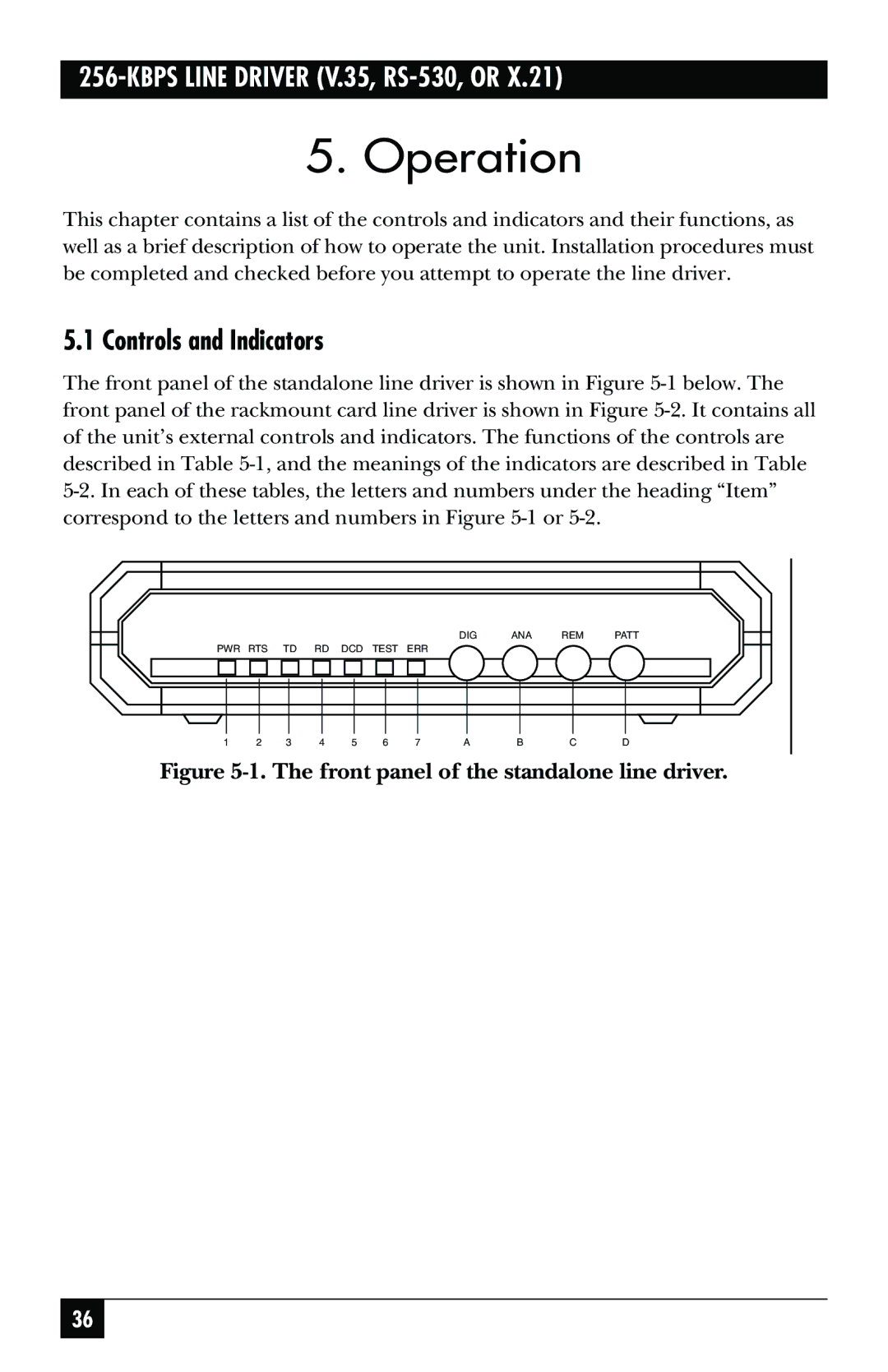
The front panel of the standalone line driver is shown in Figure
|
|
|
|
|
|
|
|
|
|
|
|
|
|
|
|
|
|
|
|
|
| DIG | ANA | REM | PATT | ||||
PWR RTS | TD |
| RD | DCD | TEST | ERR |
|
|
|
|
|
|
|
| |||||||||||||||
|
|
|
|
|
|
|
|
|
|
|
|
|
|
|
|
|
|
|
|
|
|
|
|
|
|
|
|
| |
|
|
|
|
|
|
|
|
|
|
|
|
|
|
|
|
|
|
|
|
|
|
|
|
|
|
|
|
|
|
|
|
|
|
|
|
|
|
|
|
|
|
|
|
|
|
|
|
|
|
|
|
|
|
|
|
|
|
|
|
1 | 2 |
| 3 | 4 | 5 |
| 6 |
| 7 |
| A | B | C | D | |||||||||||||||
Figure 5-1. The front panel of the standalone line driver.
36
