256-KBPS LINE DRIVER (V.35, RS-530, OR X.21)
LOCAL
DTE
REM
DEPRESSED
DATA |
|
CLK | XMTR |
CLK
DATA RCVR
RCVR
XMTR ![]()
REMOTE
DTE
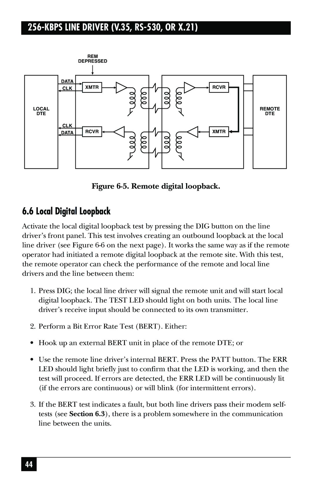
Figure 6-5. Remote digital loopback.
6.6 Local Digital Loopback
Activate the local digital loopback test by pressing the DIG button on the line driver’s front panel. This test involves creating an outbound loopback at the local line driver (see Figure
1.Press DIG; the local line driver will signal the remote unit and will start local digital loopback. The TEST LED should light on both units. The local line driver’s receive input should be connected to its own transmitter.
2.Perform a Bit Error Rate Test (BERT). Either:
•Hook up an external BERT unit in place of the remote DTE; or
•Use the remote line driver’s internal BERT. Press the PATT button. The ERR LED should light briefly just to confirm that the LED is working, and then the test will proceed. If errors are detected, the ERR LED will be continuously lit (if the errors are continuous) or will blink (for intermittent errors).
3.If the BERT test indicates a fault, but both line drivers pass their modem self- tests (see Section 6.3), there is a problem somewhere in the communication line between the units.
44
