256-KBPS LINE DRIVER (V.35, RS-530, OR X.21)
2.Verify that the DTE is operating properly and can be used for a test.
3.Perform the test using one of these methods:
•Send data from the DTE and check the echoed data stream.
•Hook up an external Bit Error Rate Test (BERT) unit in place of the DTE.
•Use the line driver’s internal BERT. Press the PATT button.The ERR LED should light briefly just to confirm that the LED is working, and then the test will proceed. If errors are detected, the ERR LED will be continuously lit (if the errors are continuous) or will blink (for intermittent errors).
4.Repeat Steps 1 through 3 at the remote site.
5.If the BERT tests show no errors, but the data echoed back to either DTE is bad, check the DTE and the cable connecting it to the line
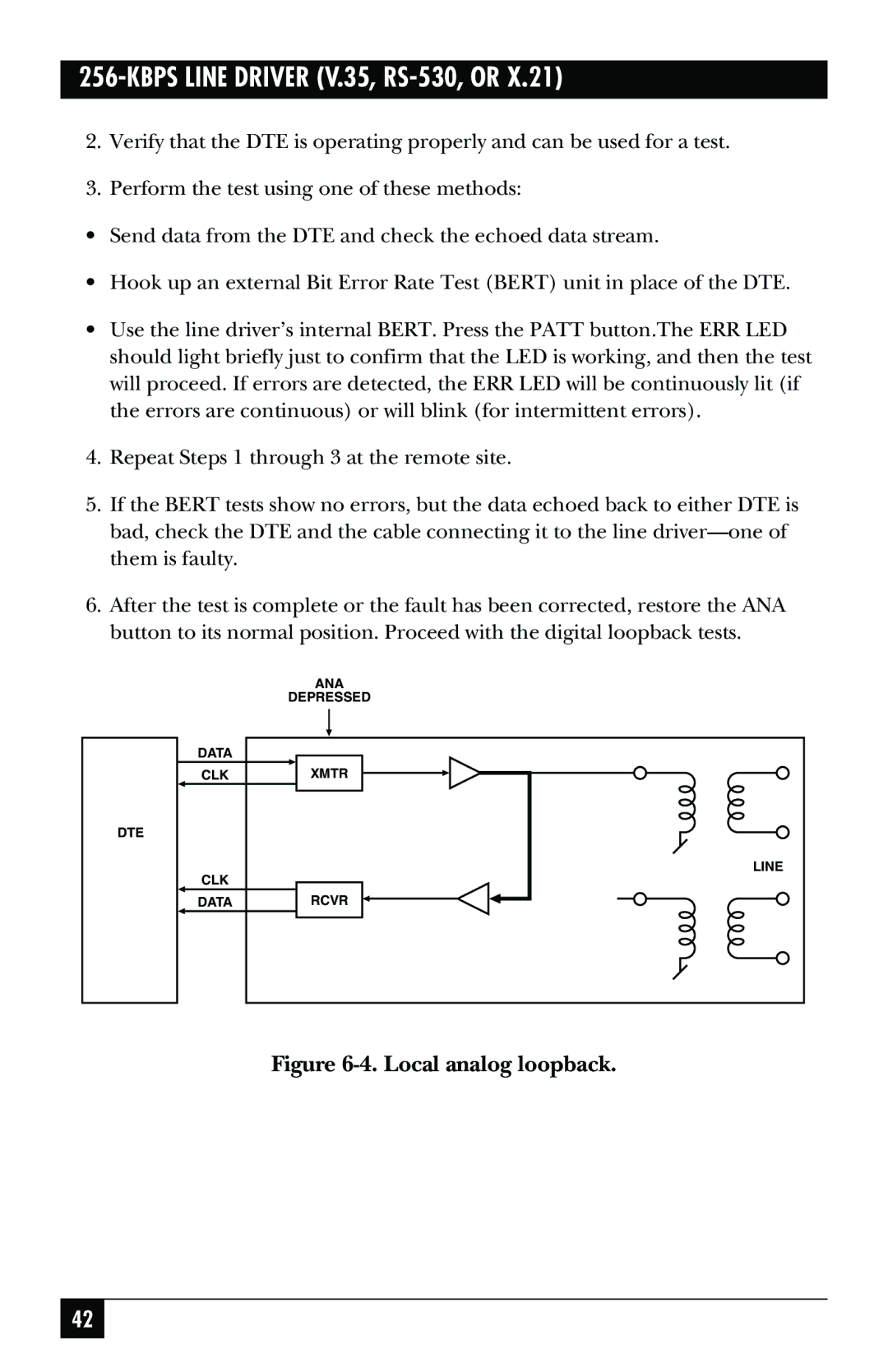
6.After the test is complete or the fault has been corrected, restore the ANA button to its normal position. Proceed with the digital loopback tests.
DTE
| ANA |
| DEPRESSED |
DATA |
|
CLK | XMTR |
CLK | LINE |
| |
DATA | RCVR |
Figure 6-4. Local analog loopback.
42
