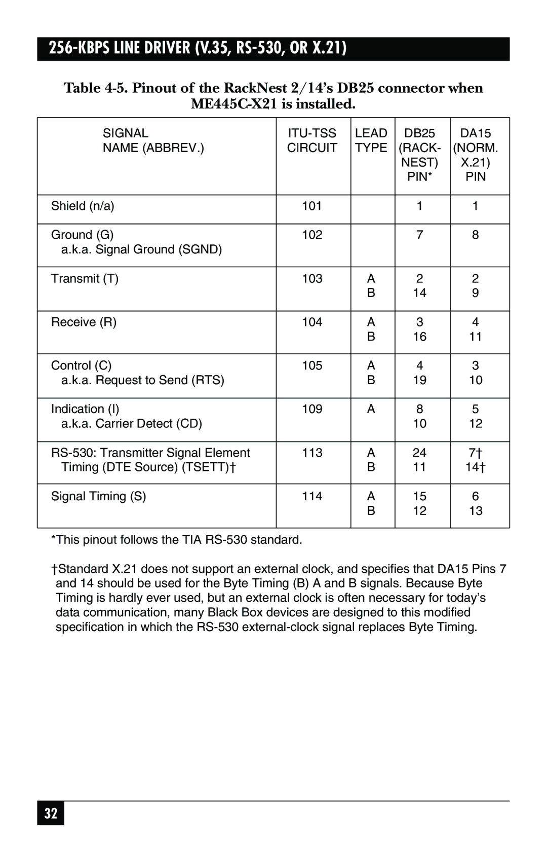
256-KBPS LINE DRIVER (V.35, RS-530, OR X.21)
Table
SIGNAL | LEAD | DB25 | DA15 | |
NAME (ABBREV.) | CIRCUIT | TYPE | (RACK- | (NORM. |
|
|
| NEST) | X.21) |
|
|
| PIN* | PIN |
|
|
|
|
|
Shield (n/a) | 101 |
| 1 | 1 |
|
|
|
|
|
Ground (G) | 102 |
| 7 | 8 |
a.k.a. Signal Ground (SGND) |
|
|
|
|
|
|
|
|
|
Transmit (T) | 103 | A | 2 | 2 |
|
| B | 14 | 9 |
|
|
|
|
|
Receive (R) | 104 | A | 3 | 4 |
|
| B | 16 | 11 |
|
|
|
|
|
Control (C) | 105 | A | 4 | 3 |
a.k.a. Request to Send (RTS) |
| B | 19 | 10 |
|
|
|
|
|
Indication (I) | 109 | A | 8 | 5 |
a.k.a. Carrier Detect (CD) |
|
| 10 | 12 |
|
|
|
|
|
113 | A | 24 | 7† | |
Timing (DTE Source) (TSETT)† |
| B | 11 | 14† |
|
|
|
|
|
Signal Timing (S) | 114 | A | 15 | 6 |
|
| B | 12 | 13 |
|
|
|
|
|
*This pinout follows the TIA
†Standard X.21 does not support an external clock, and specifies that DA15 Pins 7 and 14 should be used for the Byte Timing (B) A and B signals. Because Byte Timing is hardly ever used, but an external clock is often necessary for today’s data communication, many Black Box devices are designed to this modified specification in which the
32