CHAPTER 5: Operation
2
4
6
E
B
D
PWR
RTS
TD
RD
DCD
TEST ERR
RPF
DIG
ANA
REM
PATT
1
3
5
7
A
C
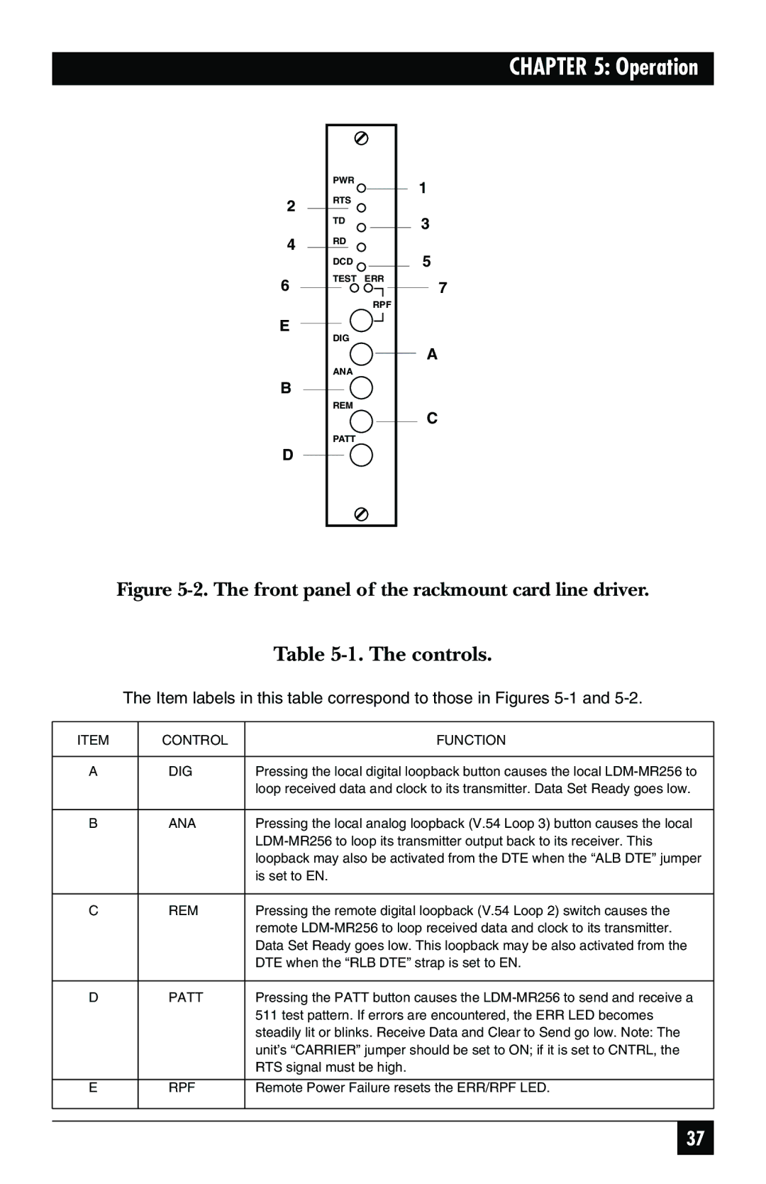
Figure 5-2. The front panel of the rackmount card line driver.
Table 5-1. The controls.
The Item labels in this table correspond to those in Figures
ITEM | CONTROL | FUNCTION |
|
|
|
A | DIG | Pressing the local digital loopback button causes the local |
|
| loop received data and clock to its transmitter. Data Set Ready goes low. |
|
|
|
B | ANA | Pressing the local analog loopback (V.54 Loop 3) button causes the local |
|
| |
|
| loopback may also be activated from the DTE when the “ALB DTE” jumper |
|
| is set to EN. |
|
|
|
C | REM | Pressing the remote digital loopback (V.54 Loop 2) switch causes the |
|
| remote |
|
| Data Set Ready goes low. This loopback may be also activated from the |
|
| DTE when the “RLB DTE” strap is set to EN. |
|
|
|
D | PATT | Pressing the PATT button causes the |
|
| 511 test pattern. If errors are encountered, the ERR LED becomes |
|
| steadily lit or blinks. Receive Data and Clear to Send go low. Note: The |
|
| unit’s “CARRIER” jumper should be set to ON; if it is set to CNTRL, the |
|
| RTS signal must be high. |
|
|
|
E | RPF | Remote Power Failure resets the ERR/RPF LED. |
|
|
|
|
|
|
37