CHAPTER 3: Configuration
3.1.4CONFIGURATION SWITCH “S3”
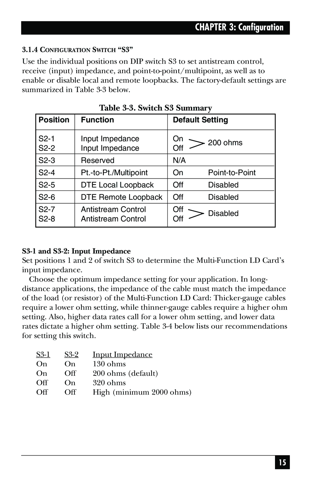
Use the individual positions on DIP switch S3 to set antistream control, receive (input) impedance, and
Table 3-3. Switch S3 Summary
Position | Function | Default Setting | ||
|
|
|
| |
Input Impedance | On | 200 ohms | ||
Input Impedance | Off | |||
| ||||
|
|
|
| |
Reserved | N/A |
| ||
On | ||||
|
|
|
| |
DTE Local Loopback | Off | Disabled | ||
|
|
|
| |
DTE Remote Loopback | Off | Disabled | ||
|
|
|
| |
Antistream Control | Off | Disabled | ||
Antistream Control | Off | |||
| ||||
|
|
|
| |
S3-1 and S3-2: Input Impedance
Set positions 1 and 2 of switch S3 to determine the
Choose the optimum impedance setting for your application. In long- distance applications, the impedance of the cable must match the impedance of the load (or resistor) of the
Input Impedance | ||
On | On | 130 ohms |
On | Off | 200 ohms (default) |
Off | On | 320 ohms |
Off | Off | High (minimum 2000 ohms) |
15
