MULTI-FUNCTION LD CARD
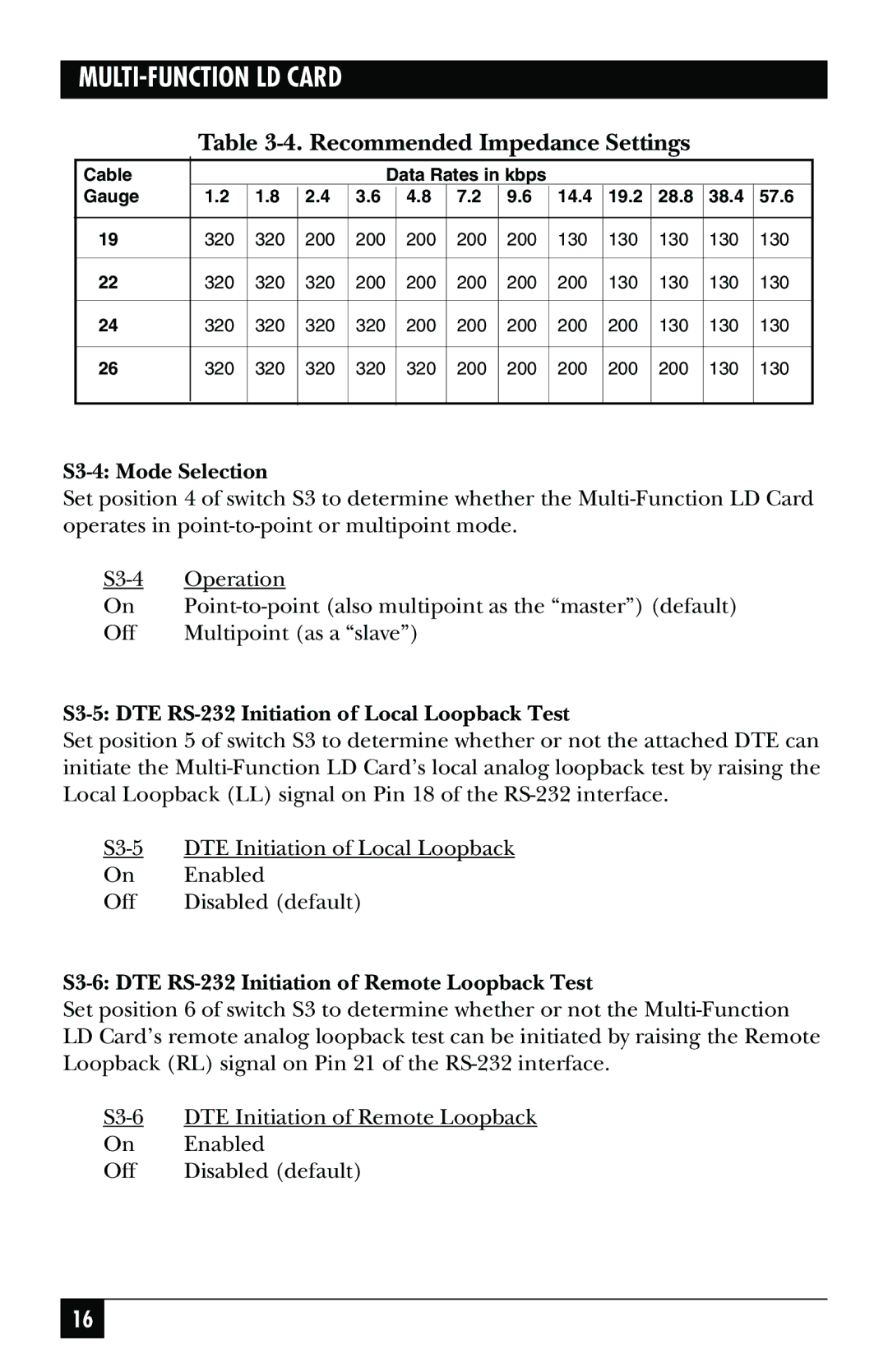
Table 3-4. Recommended Impedance Settings
Cable |
|
|
|
| Data Rates in kbps |
|
|
|
|
| |||
Gauge | 1.2 | 1.8 | 2.4 | 3.6 |
| 4.8 | 7.2 | 9.6 | 14.4 | 19.2 | 28.8 | 38.4 | 57.6 |
|
|
|
|
|
|
|
|
|
|
|
|
|
|
19 | 320 | 320 | 200 | 200 |
| 200 | 200 | 200 | 130 | 130 | 130 | 130 | 130 |
|
|
|
|
|
|
|
|
|
|
|
|
|
|
22 | 320 | 320 | 320 | 200 |
| 200 | 200 | 200 | 200 | 130 | 130 | 130 | 130 |
|
|
|
|
|
|
|
|
|
|
|
|
|
|
24 | 320 | 320 | 320 | 320 |
| 200 | 200 | 200 | 200 | 200 | 130 | 130 | 130 |
|
|
|
|
|
|
|
|
|
|
|
|
|
|
26 | 320 | 320 | 320 | 320 |
| 320 | 200 | 200 | 200 | 200 | 200 | 130 | 130 |
|
|
|
|
|
|
|
|
|
|
|
|
|
|
S3-4: Mode Selection
Set position 4 of switch S3 to determine whether the
Operation | |
On | |
Off | Multipoint (as a “slave”) |
S3-5: DTE RS-232 Initiation of Local Loopback Test
Set position 5 of switch S3 to determine whether or not the attached DTE can initiate the
DTE Initiation of Local Loopback | |
On | Enabled |
Off | Disabled (default) |
S3-6: DTE RS-232 Initiation of Remote Loopback Test
Set position 6 of switch S3 to determine whether or not the
DTE Initiation of Remote Loopback | |
On | Enabled |
Off | Disabled (default) |
16
