ServSensor EXP DC16
2.3 Hardware Description
2.3.1 Front Panel
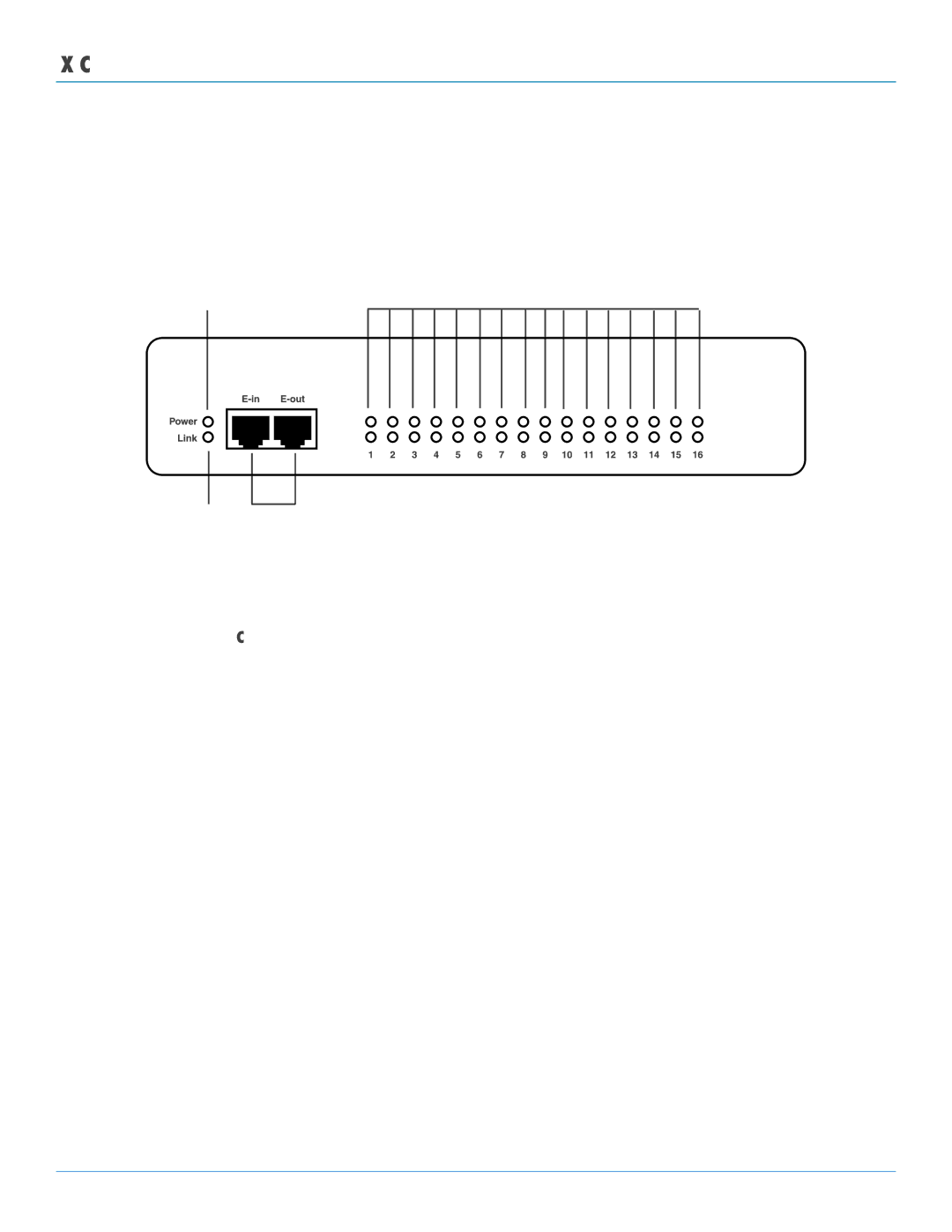
Figure 2-1 shows the ServSensor EXP DC16’s front panel, and Table 2-1 describes its components.
1
4
|
|
|
|
|
|
|
2 | 3 |
|
|
| ||
|
|
|
|
|
| Figure |
|
|
|
|
| Table | |
Number | Component | Description | ||||
1 |
| Power LED |
| Lights continuously when the ServSensor EXP DC16 is powered on. | ||
|
|
|
|
|
| If the LED is flashing, there is a problem with the CPU. |
2 |
| Link LED |
| Lights when a network connection is present. | ||
3 |
| Expansion In/Expansion Out ports. These ports are named | ||||
|
|
|
|
|
| |
|
|
|
|
|
| CAT5e |
|
|
|
|
|
| additional expansion modules via a CAT5e |
4 |
| Status/Online LEDs | LEDs numbered | |||
|
|
|
|
|
| connected to each port. These LEDs also indicate system status |
|
|
|
|
|
| during various operations. |
|
|
|
|
| Table | |
Function |
|
|
| Description |
| |
Upgrade in progress |
|
|
| The red LEDs will move from left to right to indicate activity, and the green LEDs indicate | ||
|
|
|
|
| overall progress of the upgrade. When all the red lights are off and all the green lights are | |
|
|
|
|
| on, the upgrade/recovery process is complete. | |
Unit is operating in safe mode | Used when the ServSensor EXP DC16 loads the operating system (OS) with a minimal set | |||||
|
|
|
|
| of drivers. If your device enters safe mode after rebooting, contact Black Box Technical | |
|
|
|
|
| Support at | |
Unit is in recovery mode | The ServSensor EXP DC16 may enter recovery mode if a firmware upgrade is incomplete. | |||||
|
|
|
|
| The unit displays a continuously lit row of red LEDs during recovery mode. If your device | |
|
|
|
|
| enters recovery mode, contact Black Box Technical Support at | |
|
|
|
|
| info@blackbox.com. | |
Page 8 |