10 en Inserting the Language Tab |
|
|
|
|
|
|
| Remote Command Center | |
|
|
|
|
|
|
|
|
|
|
|
|
|
|
|
|
|
|
|
|
|
|
|
|
|
|
|
|
|
|
|
|
|
|
|
|
|
|
|
|
|
|
|
|
|
|
|
|
|
|
|
|
|
|
|
|
|
|
|
|
|
|
|
|
|
|
|
|
|
|
|
|
|
|
|
|
|
|
|
|
|
|
|
|
|
|
|
|
|
|
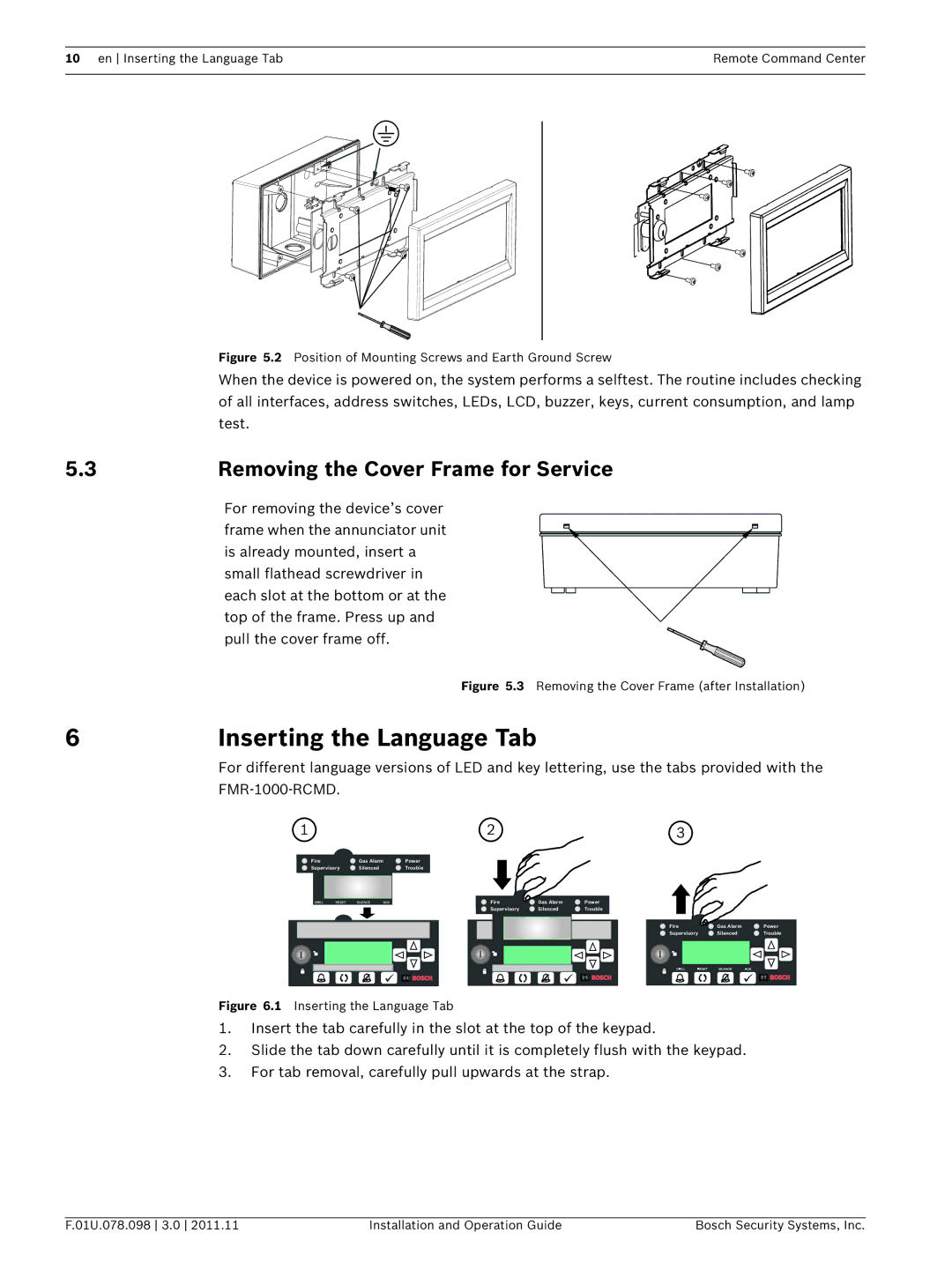
Figure 5.2 Position of Mounting Screws and Earth Ground Screw
When the device is powered on, the system performs a selftest. The routine includes checking of all interfaces, address switches, LEDs, LCD, buzzer, keys, current consumption, and lamp test.
5.3 | Removing the Cover Frame for Service |
For removing the device’s cover frame when the annunciator unit is already mounted, insert a small flathead screwdriver in each slot at the bottom or at the top of the frame. Press up and pull the cover frame off.
Figure 5.3 Removing the Cover Frame (after Installation)
6 | Inserting the Language Tab |
For different language versions of LED and key lettering, use the tabs provided with the
1 |
| 2 |
| 3 |
Fire | Gas Alarm | Power |
|
|
Supervisory | Silenced | Trouble |
|
|
|
| Fire | Gas Alarm | Power |
|
| Supervisory | Silenced | Trouble |
Fire | Gas Alarm | Power |
Supervisory | Silenced | Trouble |
Figure 6.1 Inserting the Language Tab
1.Insert the tab carefully in the slot at the top of the keypad.
2.Slide the tab down carefully until it is completely flush with the keypad.
3.For tab removal, carefully pull upwards at the strap.
F.01U.078.098 3.0 2011.11 | Installation and Operation Guide | Bosch Security Systems, Inc. |
