8 en Mounting | Remote Command Center |
|
|
Before mounting the unit, follow the instructions in
–Section 6 Inserting the Language Tab on Page 10
–Section 7 Address Setting on Page 11
–Section 5 Wiring on Page 9.
![]()
![]() 1 1.02 in. (26 mm)
1 1.02 in. (26 mm)![]()
![]()
4.41 in. (112 mm)
| 5 |
| 5 |
| 5.5 in. (140 mm) |
| |
3 | 2 | 1 | 3 |
|
| 4 | |
|
|
| |
| 5 |
| 5 |
7.40 in. (188 mm)
1.02 in. (26 mm)
7/8 in. (20 mm) ![]()
![]() 1
1
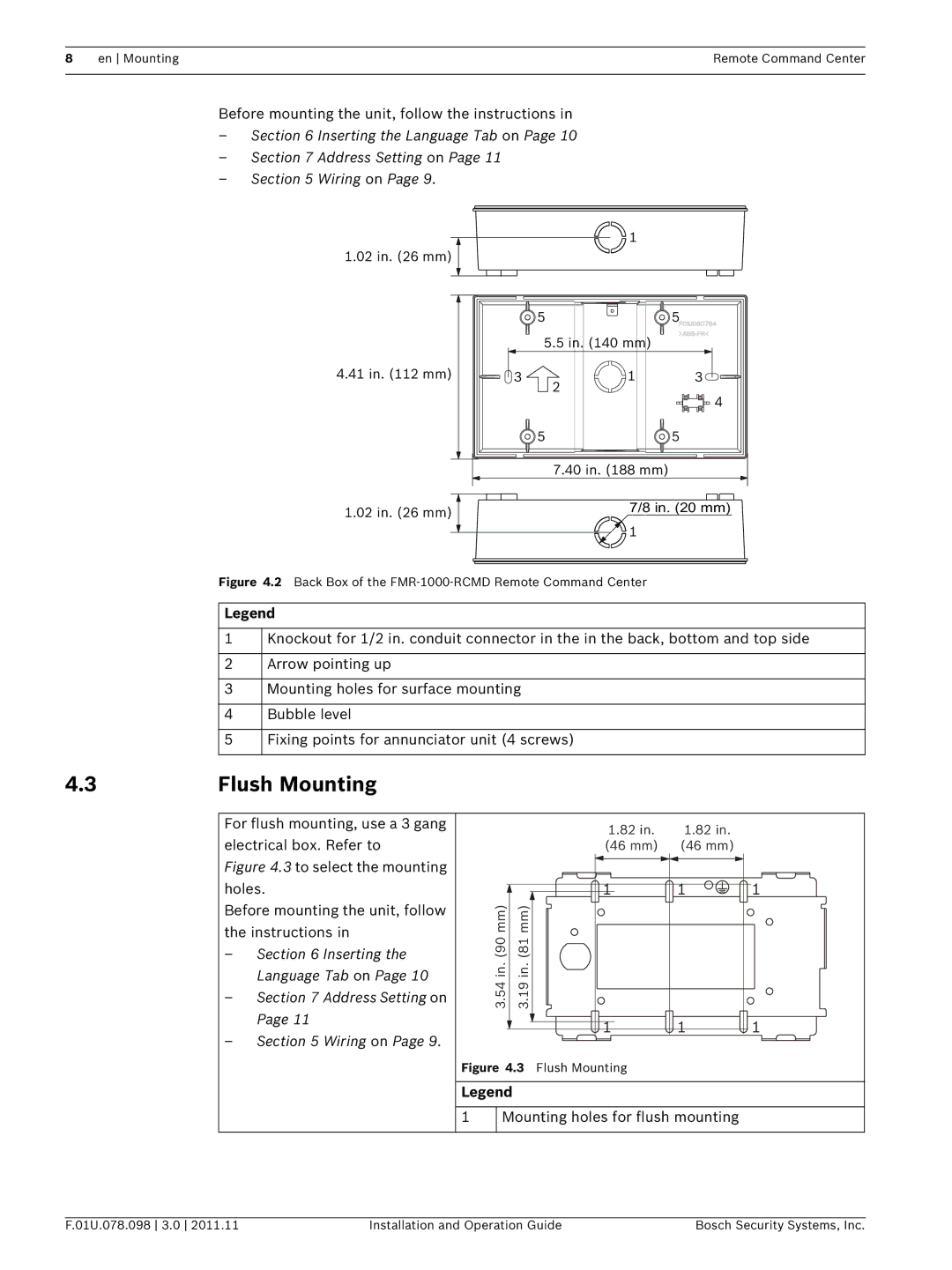
Figure 4.2 Back Box of the FMR-1000-RCMD Remote Command Center
Legend
1
2
3
4
5
Knockout for 1/2 in. conduit connector in the in the back, bottom and top side
Arrow pointing up
Mounting holes for surface mounting
Bubble level
Fixing points for annunciator unit (4 screws)
4.3 | Flush Mounting |
For flush mounting, use a 3 gang electrical box. Refer to
Figure 4.3 to select the mounting holes.
Before mounting the unit, follow the instructions in
–Section 6 Inserting the Language Tab on Page 10
–Section 7 Address Setting on Page 11
–Section 5 Wiring on Page 9.
1.82 in. | 1.82 in. |
(46 mm) | (46 mm) |
| 1 | 1 | 1 |
3.54 in. (90 mm) | 3.19 in. (81 mm) |
|
|
| 1 | 1 | 1 |
Figure 4.3 Flush Mounting
Legend
1Mounting holes for flush mounting
F.01U.078.098 3.0 2011.11 | Installation and Operation Guide | Bosch Security Systems, Inc. |