DVR-940HX-S DVR-545HX-S
Thank you for buying this Pioneer product
Risk of Electric Shock Do not Open
Ventilation Caution
POWER-CORD Caution
Operating Environment
Contents
Initial Setup menu
Copying and backup
Using the Jukebox
Disc Setup menu
Before you start Chapter
Putting the batteries in the remote control
Before you start
What’s in the box
Compatible media
Before you start Using the remote control
Disc / content format playback compatibility
Model Playable
Is a trademark of DVD Format/Logo Licensing Corporation
Before you start
DVD/HDD Recording and playback compatibility
Other disc compatibility
Using DVD-R DL/DVD+R DL discs
About DualDisc playback
CD-R/-RW compatibility
WMA Windows Media Audio compatibility
Compressed audio compatibility
DivX video compatibility
File structure Up to 99 folders or 999 files
PC-created disc compatibility
DivX VOD content
Jpeg file compatibility
Dolby Digital
About the internal/external hard disk drive
DVB
Optimizing HDD performance
Symbols used in this manual
Using the external HDD
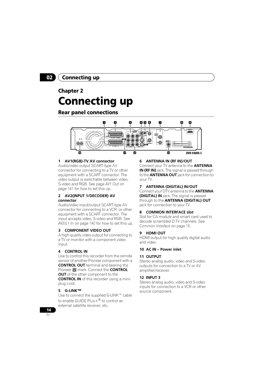
Rear panel connections
Connecting up
Connecting up Chapter
Common Interface
Connecting up
Front panel connections
Inserting a CA module
Connecting up Connecting a TV antenna
Output
Connect your TV antenna to the recorder and TV
Connecting up Easy connections
See Connecting a TV antenna on page 16 for details
Connecting up Using other types of audio/ video output
Connect the Video Output jack to a video input on your TV
This enables you to watch discs
This enables you to record scrambled TV Channels
Plug the supplied G-LINK cable to the G-LINK jack
Connecting up Connecting an external decoder box
Scart AV Connector
CH Setting on
This enables you to listen to multichannel surround sound
Connecting up Connecting to an AV amplifier/receiver
This enables you to watch and record TV channels
Connecting up Connecting using Hdmi
Hdmi
About Hdmi
Connecting other AV sources
Connecting a VCR or analog camcorder
Using a USB printer
Connecting a USB device
Connecting a DV camcorder
Jpeg file storage devices
Plugging
Connecting up Connecting the optional
See also Using the external HDD on
External HDD DVR-940HX-S only
Front panel
Controls and displays
Controls and displays Chapter
Input Select
Controls and displays
Help
LP / SLP
Controls and displays Display
Ntsc
EP / SEP
Prev Next
Controls and displays Remote control DVR-940HX-S
Pause
Stop REC
RED, GREEN, YELLOW, Blue
REC
Info
24 TV/DVD
Remote control DVR-545HX-S
Text
Enter
TV / D.TV
Play Mode
Press to pause playback or recording Recording controls
Number buttons, Clear
Press to change the channel of the built- in TV tuner
19 TV/DVD
Getting started Chapter
Switching on and setting up
Getting started
Getting started
Auto-tuning channels
Auto clock setting
Select your country
Time zone
Manual clock setting
Use
Select the EPG Electronic Program Guide type to use
Enter Press to continue after reading the HDD caution
For users receiving digital broadcast services
Return to automatic clock setting
Home Menu Press Home Menu
Getting started Setting up the Guide Plus+ system
Guide Display the Guide Plus+ setup menu
After pressing Enter Select your reception method
See also Guide Plus+ FAQ and troubleshooting on
Code
Terrestrial, Cable or Satellite
About EPG download
Country Host Comments Region Channels
Numbers as you like
Checking the downloaded data the following day
Guide Display the Guide Plus+ screen
Legal Notice
Using the Guide Plus+ electronic program guide Chapter
Guide Plus+ system
Guide Plus+ navigation
Lock / Unlock video window
Using the Guide Plus+ electronic program guide
One-Button-Record
Highlight a program title
Browsing the Grid
Areas
Channel mosaic screen Grid Area
Next Previous / next
Searching
Using My Choice keywords for a search
Search Area
Enter Start the keyword search
Setting up a profile
My TV Area
Channels is now highlighted
Press Enter to activate your profile
Schedule Area
Editing a scheduled recording
Highlight the left tile of a scheduled recording
Enter a name for the scheduled recording
Press to access the extended recording options
Press Enter to confirm
Setting a Video Plus+ recording
Deleting a scheduled recording
Setting a manual recording
About timer recording
Press and hold for three seconds during a timer recording
Extending a timer recording in progress
Stopping a timer recording
Select ‘Yes’ to confirm
Info Area
Switching a channel on/off
Frequently Asked Questions
Editor Area
Select ‘Setup’ from the Menu bar
Setup Area
Making changes to your Guide Plus+ setup
Changing the source and program number
FAQ
Guide Plus+ FAQ and troubleshooting
Manual Host Channel setup
Hours I still have a blank EPG what is
According to your preferences. Access
Source and preset number according to
Connecting up on page 14 to double
TV listings information doesn’t update
Digital EPG system
Using the digital electronic program guide
Using the digital electronic program guide Chapter
General Program List
Program information
Using the digital electronic program guide
Using the Digital EPG
Setting timer programs
EPG Jump
Select ‘OK’
EPG Search
Within one week to search
Results of your search are displayed
About DVD recording
Recording
Recording Chapter
Disc type/rec Max. titles
About HDD recording
HDD Video mode compatibility
Recording
Recording to DVD-R DL/DVD+R DL discs
Recording equipment and copyright
Recording Recorded audio
Restrictions on video recording
Changing channels
Recording Using the built-in A.TV and D.TV tuners
Switching between A.TV and D.TV tuners
Channel +
Changing D.TV audio languages
Using the Mheg application
Displaying a channel banner
Changing D.TV subtitle languages
Changing A.TV audio channels
Switching between TV and DVD
Switch between TV mode and DVD mode
Press to change the audio type
Recording Setting the picture quality/ recording time
Press repeatedly to select the recording quality
Set the picture quality/recording time
Recording Basic recording from the TV
Select the HDD1 or DVD for recording
Select a TV channel to record
Start recording
Press to stop recording
Using the recorder’s internal tuner for Pause Live TV
Setting up for Pause Live TV
TV tuner setup for Pause Live TV
Recording Pause Live TV
Live TV Start recording the current TV channel
Using Pause Live TV
Operation table
Recording continues with playback paused
Stop
Recording Simultaneous recording and playback Chase Play
Another title to play
Recording will continue To stop recording, press
Recording Recording from an external component
Playing your recordings on other DVD players
Finalizing a disc
Select ‘Finalize’ ‘Finalize’ ‘Next Screen’
Recording.1
Recorder will now start finalizing the disc
DVD-R DVD-RW DVD+RW DVD-RAM
Select ‘Start’
Introduction
Playback
Playback Chapter
Basic playback
Playing DVD discs
Except VR mode During play
Playback
Start playback
Playing from the HDD
DVR-545HX-S Press to skip
Playing CDs and WMA/MP3 discs
Playing Video CD/Super VCDs
Playing DivX video files
Using the Disc Navigator to browse the contents of a disc
Using the Disc Navigator with playback-only discs
Scanning discs
DVD HDD Video CD Super VCD DivX
Playback Playing in slow motion
Frame advance/frame reverse
Resume normal playback
DVD HDD CD Video CD DivX
Search Mode
Repeat
Enter a title/chapter/folder
Repeat play
Program play
DVD-Video DivX
Displaying and switching subtitles
Switching DVD and DivX soundtracks
Change the audio soundtrack
HDD DVD VR DVD-RAM
Playback Switching audio channels
Switching camera angles
Display/change the on-screen information
Playback Displaying disc information on-screen
HDD and removable disc activity display
Playing from a DV camcorder
Playing and recording from a DV camcorder
Playing and recording from a DV camcorder Chapter
Recording from a DV camcorder
Playing and recording from a DV camcorder
Select ‘Start Rec’
Can’t get my DV camcorder to work with the recorder
DV video setting
About DV
There’s a picture, but no sound
Editing Chapter
VR mode
Editing
Editing options
Editing Disc Navigator screen
Select the HDD1 or DVD Disc Display the Disc Navigator
HDD genres
Editing
Editing accuracy
Create
Erase
Title Name
Using the remote key shortcuts to input a name
Key Characters
Set Thumbnail
Erase Section
Divide
Chapter Edit
Select ‘Edit’ ‘Chapter Edit’ from the command menu panel
Select the command you want
DVD VR DVD-RAM HDD
Lock
Editing10
Set Genre
Title to move
Move
Combine
Insert position
Genre Name
Definable genre names
Selected titles are marked with a
Select ‘Undo’ from Command menu panel
Undo
DVD Video DVD VR DVD+R DVD+RW
Restrictions on copying
Copying and backup
Copying and backup Chapter
Copyright
Copying and backup One Touch Copy
Canceling One Touch Copy
Copying from HDD to DVD
Copying and backup
Using Copy Lists
Select ‘HDD DVD’
HDD DVD
Select ‘Next’ to move on to the Title Edit screen
Press to display the command menu panel
Display the command menu panel
Select ‘Next’ to proceed
Copying
‘HDD2
Copying from DVD to internal
HDD’
Select a recording mode for Copy
Recording Mode
Select ‘Recording Mode’ from the command menu panel
Select ‘Start Copy’ to start Copying
Bilingual
Using disc backup
Select a backup option
Select a bilingual audio Option
To see the progress of the backup, press
118
Copying music to the HDD
Using the Jukebox
Using the Jukebox Chapter
Select ‘DVD/CD to HDD’
Playing music from the Jukebox
Using the Jukebox Copying files from a USB device
Select ‘Copy Album’ from the command menu panel
Select ‘Listen to Music from USB Device’
Changing the album view
Using the Jukebox
Editing Jukebox albums
Locating Jpeg picture files
PhotoViewer
PhotoViewer Chapter
Select ‘PhotoViewer’ from the Home Menu
PhotoViewer Playing a slideshow
Reloading files from a disc or USB device
Zooming an image
PhotoViewer
Importing files to the HDD
Rotating an image
Selecting multiple files or folders
Enter Display the command menu
Importing files from a USB device
Select the folder containing Files you want to import
Creating a new folder
PhotoViewer Copying selected files to a DVD-R/-RW
Editing files on the HDD
Erasing a file or folder
Copying files
Naming files and folders
Locking/Unlocking files
PhotoViewer Printing files
Select ‘Start’ to confirm, or ‘Cancel’ to cancel
Once printing has started, you can cancel by pressing Enter
Select the files you want to Print
Basic settings
Disc Setup menu
Disc Setup menu Chapter
Lock Disc
Finalize
Disc Setup menu Initialize settings
Finalize settings
Undo Finalize
Disc Setup menu Optimize HDD Initialize HDD
Setting the picture quality for TV and external inputs
Video Adjust menu
Video Adjust menu Chapter
Choosing a preset
Chroma Level Adjusts how rich the colours appear
Video Adjust menu
Select the setting you want to Adjust
Select the picture quality setting you want to adjust
Move the cursor down and select ‘Detailed Settings’
Select a setting
Professional
Gamma Correction Adjusts the brightness of darker images
Using the Initial Setup menu
Initial Setup menu
Initial Setup menu Chapter
Setting Options Explanation
Initial Setup menu
Channel Sort Next Screen
Signal Check Next Screen
Aerial Power
Channel Options Next Screen
Analog Tuner Auto Channel Auto Scan
Manual CH Setting Next Screen
TV Language Next Screen
Download from
RGB
Nicam
Mpeg PCM
PCM
Mpeg
Other
Language OSD Language English
Audio Language English
Subtitle Language English
Guages for language options on
DVD Menu Subtitle
Language
SEP can be set
DVD+R/+RW
Change Password
Angle Indicator
Parental Lock Set Password Next Screen
Playback TV Screen Size Letter Box
720 x
Screen Resolution 1920 x 1080p Constant 1920 x 1080p output
Line system
Video Output Full
Audio Output Auto
Video Priority Mode Hdmi
Remote Control Recorder
Component
AV. Link This Recorder
Additional information about the TV system settings
About the input line system
Only
About Ntsc on PAL TV
Selecting other languages for language options
Additional information about component video output
About the input colour system
Auto Update
Initial Setup menu Using Software Update Digital tuner
Manual Update
Technical Information
Additional information
Setting up the remote to control your TV DVR-940HX-S
Using the TV remote control buttons
Additional information Chapter
Mode
Additional information Minimum copying times
DVD disc type Rec
SEP
Additional information Manual recording modes
Additional information
Troubleshooting
Problem Remedy
General
Gual program
Cannot switch a bilin
No sound or sound is distorted
Picture from
158
Copy DVD to HDD
Shows ‘LOCK’ when a Button is pressed Can’t use One Touch
Copy HDD to DVD
Front panel
ProblemRemedy
Message Explanation/Action
This can be done using Disc Setup
Repairing disc
Repairing the HDD
Message Setting of the recorder
DV camcorder at a time
Camcorder is in camera mode. Switch it to playback mode
Message
Language Language code letter, Language code
Additional information Language code list
Country/Area code list
Country/Area, Country/Area code, Code letter
When viewing on a widescreen TV or monitor
When viewing on a standard TV or monitor
Pan & Scan Setting
Setting Appearance 169 Program is presented in widescreen
Storing discs
Cleaning the pickup lens
Additional information Handling discs
Damaged discs
Additional information Condensation
Hints on installation
Resetting the recorder
Moving the recorder
Tuner analog
Additional information Specifications
Timer
Input/Output
Supplied accessories
Tuner digital
170
171
Pioneer Corporation