Remote Command Center | Troubleshooting en 15 |
|
|
pattern, or they fully
If programmed, the panel transmits a silence report to the central station.
If the panel is already silenced, pressing [SILENCE] again causes an unsilence command in the panel. Silence operation does not reset the alarm status and does not return the activated input to normal service. Any new alarm reactivates any silenced outputs.
Trouble Reminder
If any events are not cleared within 24 hours after the [SILENCE] or [ACK] key was pressed, the panel turns on the piezo again and events are transmitted to the central station again.
Reset
Pressing the reset key turns off the piezo and all activated or silenced outputs. The reset operation turns off auxiliary power AUX/RST for 5 seconds, and activates the global resetting zone. All alarms, supervisories, and troubles caused by activation of SLC points are cleared. Then the panel tries to reset all points that are in
Any alarm or trouble that exists after a reset causes the system to sound again.
Drill
To activate the drill operation, the [DRILL] key must be pressed twice to prevent accidental activation. Pressing the key once the system prompts for confirmation. Pressing the [DRILL] key again turns on all unbypassed NACs and drillable relay outputs.
The drill operation stops if the reset key is pressed, or it is automatically cancelled if the operation was started for a programmed time. A system reset is automatically performed by stopping the drill so that the panel and all field devices restore to their normal operation.
If programmed, a drill start report and a drill stop report are transmitted to the central station.
10 | Troubleshooting |
|
|
| |
|
|
|
|
|
|
|
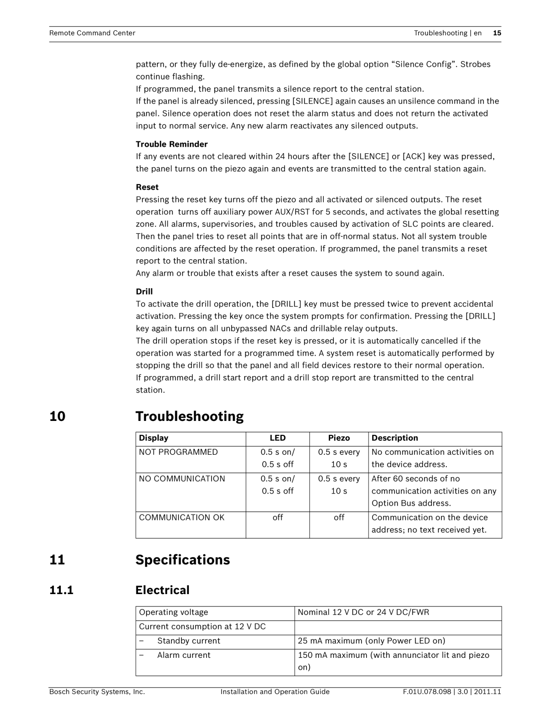
| Display | LED | Piezo | Description |
|
|
|
|
|
|
|
| NOT PROGRAMMED | 0.5 s on/ | 0.5 s every | No communication activities on |
|
|
| 0.5 s off | 10 s | the device address. |
|
|
|
|
|
|
|
| NO COMMUNICATION | 0.5 s on/ | 0.5 s every | After 60 seconds of no |
|
|
| 0.5 s off | 10 s | communication activities on any |
|
|
|
|
| Option Bus address. |
|
|
|
|
|
|
|
| COMMUNICATION OK | off | off | Communication on the device |
|
|
|
|
| address; no text received yet. |
|
|
|
|
|
|
11 | Specifications |
| ||
11.1 | Electrical |
| ||
|
|
|
| |
|
| Operating voltage | Nominal 12 V DC or 24 V DC/FWR | |
|
|
|
| |
|
| Current consumption at 12 V DC |
| |
|
|
|
|
|
|
| – | Standby current | 25 mA maximum (only Power LED on) |
|
|
|
|
|
|
| – | Alarm current | 150 mA maximum (with annunciator lit and piezo |
|
|
|
| on) |
|
|
|
|
|
Bosch Security Systems, Inc. | Installation and Operation Guide | F.01U.078.098 3.0 2011.11 |