36 en Settings Tree OptionsCTFID
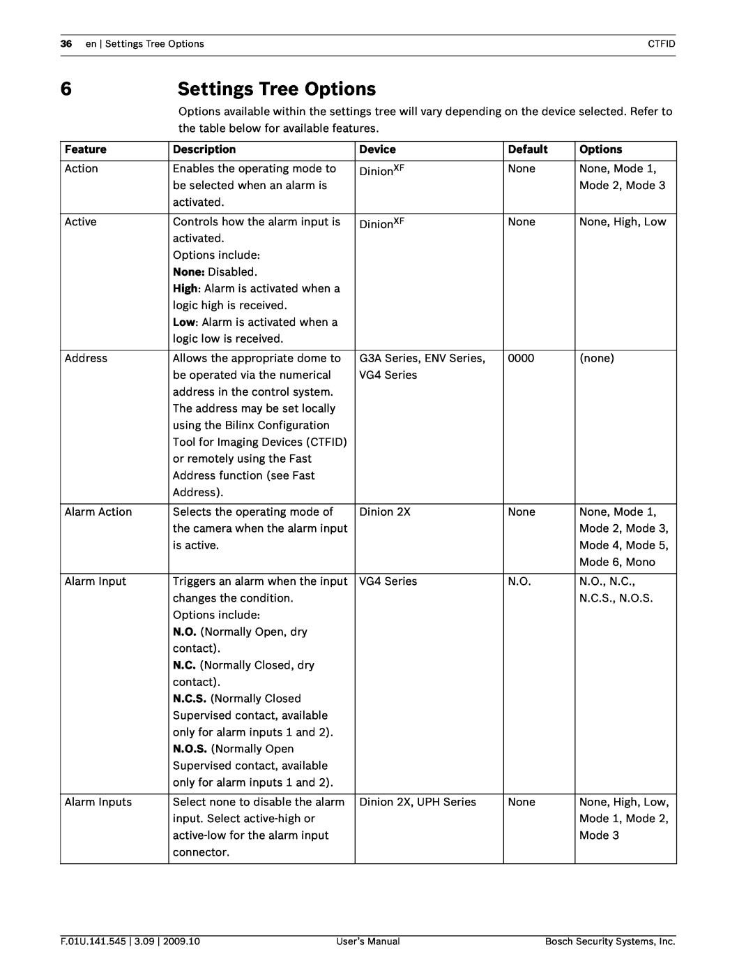
6 | Settings Tree Options |
|
| |
| Options available within the settings tree will vary depending on the device selected. Refer to | |||
| the table below for available features. |
|
| |
|
|
|
|
|
Feature | Description | Device | Default | Options |
|
|
|
|
|
Action | Enables the operating mode to | DinionXF | None | None, Mode 1, |
| be selected when an alarm is |
|
| Mode 2, Mode 3 |
| activated. |
|
|
|
|
|
|
|
|
Active | Controls how the alarm input is | DinionXF | None | None, High, Low |
| activated. |
|
|
|
| Options include: |
|
|
|
| None: Disabled. |
|
|
|
| High: Alarm is activated when a |
|
|
|
| logic high is received. |
|
|
|
| Low: Alarm is activated when a |
|
|
|
| logic low is received. |
|
|
|
|
|
|
|
|
Address | Allows the appropriate dome to | G3A Series, ENV Series, | 0000 | (none) |
| be operated via the numerical | VG4 Series |
|
|
| address in the control system. |
|
|
|
| The address may be set locally |
|
|
|
| using the Bilinx Configuration |
|
|
|
| Tool for Imaging Devices (CTFID) |
|
|
|
| or remotely using the Fast |
|
|
|
| Address function (see Fast |
|
|
|
| Address). |
|
|
|
|
|
|
|
|
Alarm Action | Selects the operating mode of | Dinion 2X | None | None, Mode 1, |
| the camera when the alarm input |
|
| Mode 2, Mode 3, |
| is active. |
|
| Mode 4, Mode 5, |
|
|
|
| Mode 6, Mono |
|
|
|
|
|
Alarm Input | Triggers an alarm when the input | VG4 Series | N.O. | N.O., N.C., |
| changes the condition. |
|
| N.C.S., N.O.S. |
| Options include: |
|
|
|
| N.O. (Normally Open, dry |
|
|
|
| contact). |
|
|
|
| N.C. (Normally Closed, dry |
|
|
|
| contact). |
|
|
|
| N.C.S. (Normally Closed |
|
|
|
| Supervised contact, available |
|
|
|
| only for alarm inputs 1 and 2). |
|
|
|
| N.O.S. (Normally Open |
|
|
|
| Supervised contact, available |
|
|
|
| only for alarm inputs 1 and 2). |
|
|
|
|
|
|
|
|
Alarm Inputs | Select none to disable the alarm | Dinion 2X, UPH Series | None | None, High, Low, |
| input. Select |
|
| Mode 1, Mode 2, |
|
|
| Mode 3 | |
| connector. |
|
|
|
|
|
|
|
|
F.01U.141.545 3.09 2009.10 | User’s Manual | Bosch Security Systems, Inc. |