BM 2610034445
 03-14_FNH180 3/27/14 11:52 AM Page 19
| Replacing Return System |
| Read instruction manual first! Remove battery pack and nails from the tool |
! WARNING | |
| before making adjustments, assembling accessories or servicing. |
|
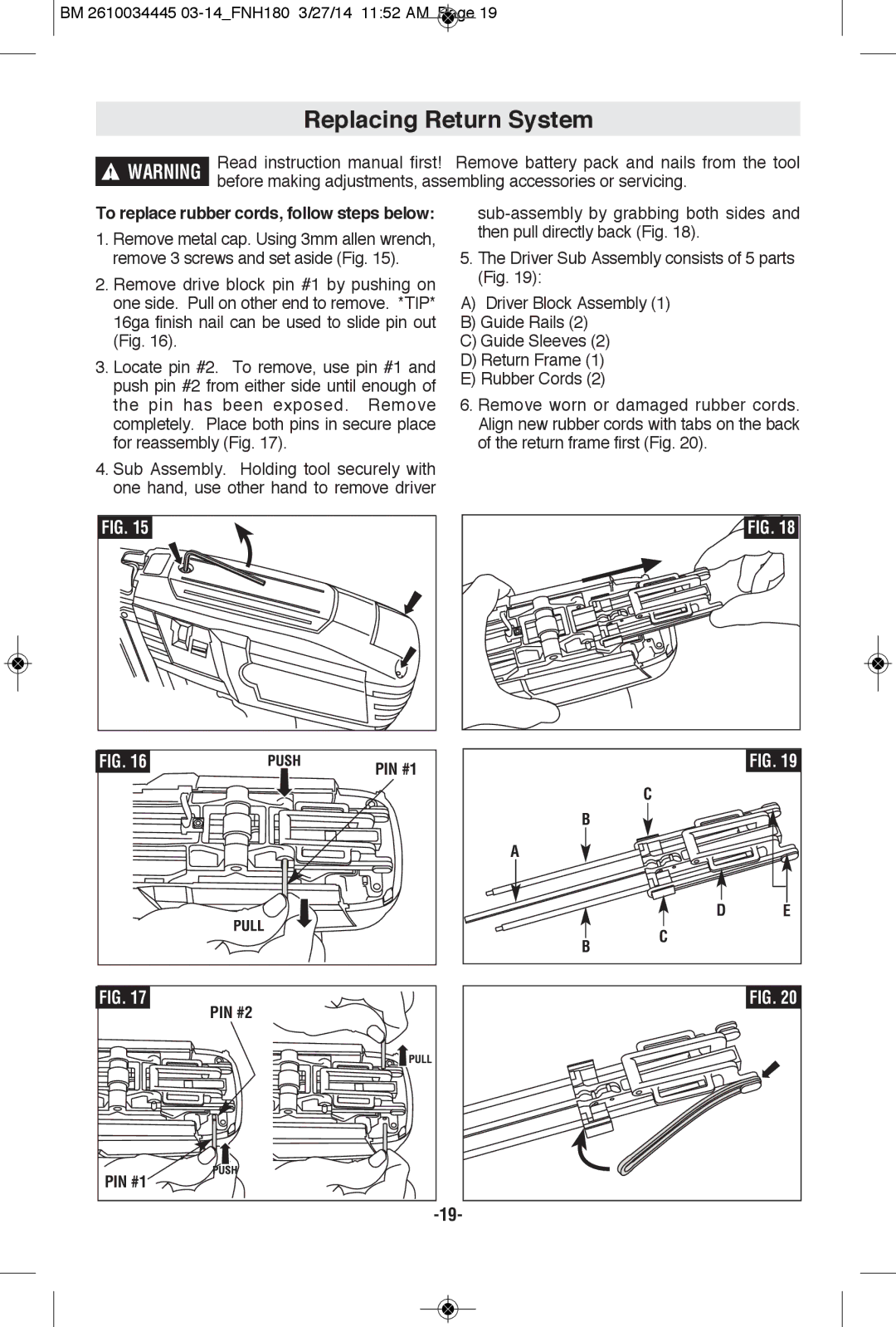
To replace rubber cords, follow steps below:
1.Remove metal cap. Using 3mm allen wrench, remove 3 screws and set aside (Fig. 15).
2.Remove drive block pin #1 by pushing on one side. Pull on other end to remove. *TIP* 16ga finish nail can be used to slide pin out (Fig. 16).
3.Locate pin #2. To remove, use pin #1 and push pin #2 from either side until enough of the pin has been exposed. Remove completely. Place both pins in secure place for reassembly (Fig. 17).
4.Sub Assembly. Holding tool securely with one hand, use other hand to remove driver
5.The Driver Sub Assembly consists of 5 parts (Fig. 19):
A)Driver Block Assembly (1)
B)Guide Rails (2)
C)Guide Sleeves (2)
D)Return Frame (1)
E)Rubber Cords (2)
6.Remove worn or damaged rubber cords. Align new rubber cords with tabs on the back of the return frame first (Fig. 20).
FIG. 15 |
|
FIG. 16 | PIN #1 |
|
FIG. 18 |
|
| FIG. 19 |
| C |
|
B |
|
|
A |
|
|
| D | E |
B | C |
|
|
|
FIG. 17 | FIG. 20 |
| PIN #2 |
PIN #1 |
|
|