![]() BM 2610034445
BM 2610034445
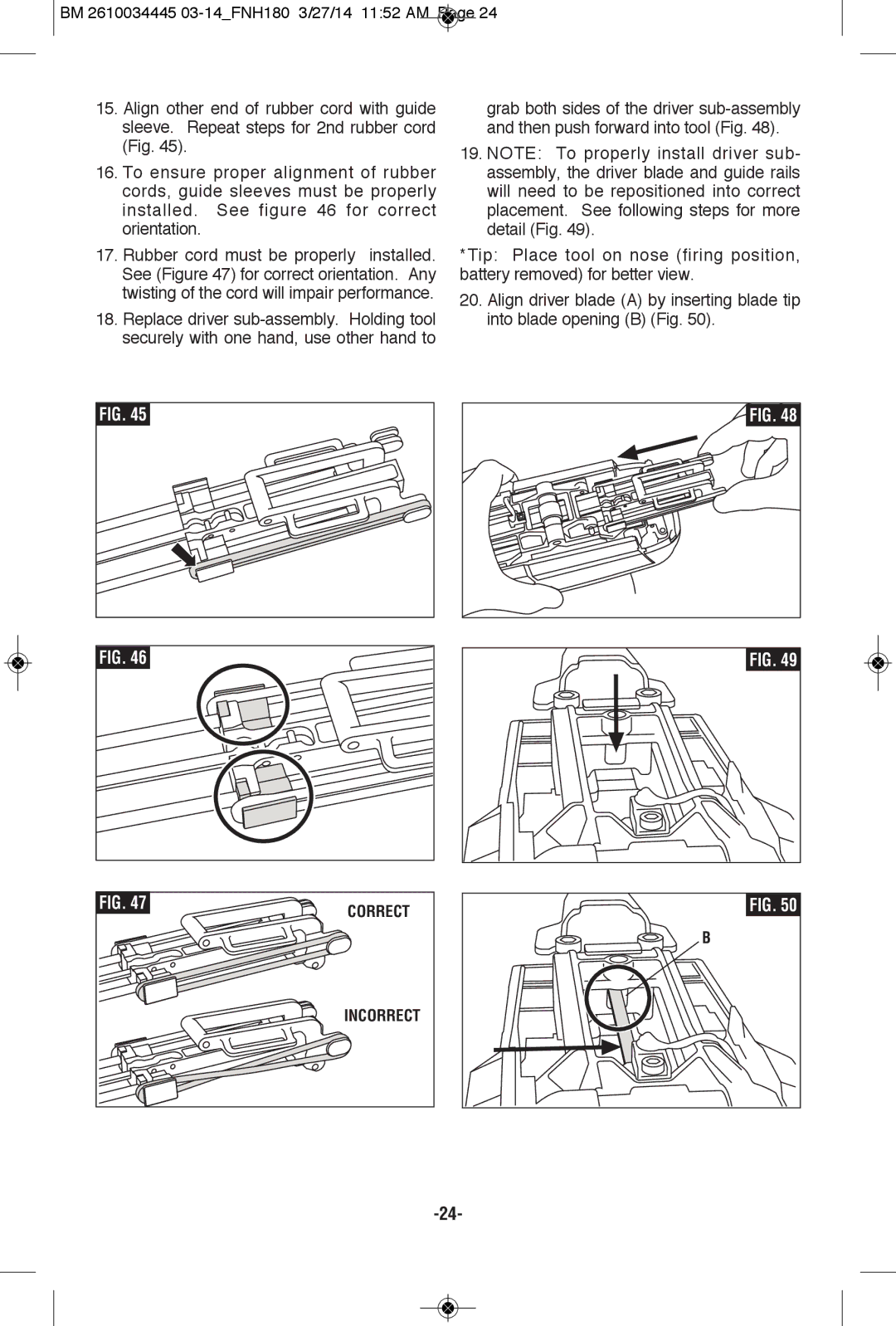
15.Align other end of rubber cord with guide sleeve. Repeat steps for 2nd rubber cord (Fig. 45).
16.To ensure proper alignment of rubber cords, guide sleeves must be properly installed. See figure 46 for correct orientation.
17.Rubber cord must be properly installed. See (Figure 47) for correct orientation. Any twisting of the cord will impair performance.
18.Replace driver
grab both sides of the driver
19.NOTE: To properly install driver sub- assembly, the driver blade and guide rails will need to be repositioned into correct placement. See following steps for more detail (Fig. 49).
*Tip: Place tool on nose (firing position, battery removed) for better view.
20.Align driver blade (A) by inserting blade tip into blade opening (B) (Fig. 50).
FIG. 45
FIG. 48
FIG. 46
FIG. 49 |
FIG. 47 | CORRECT |
| |
| INCORRECT |
FIG. 50 |
B |