Series Connections
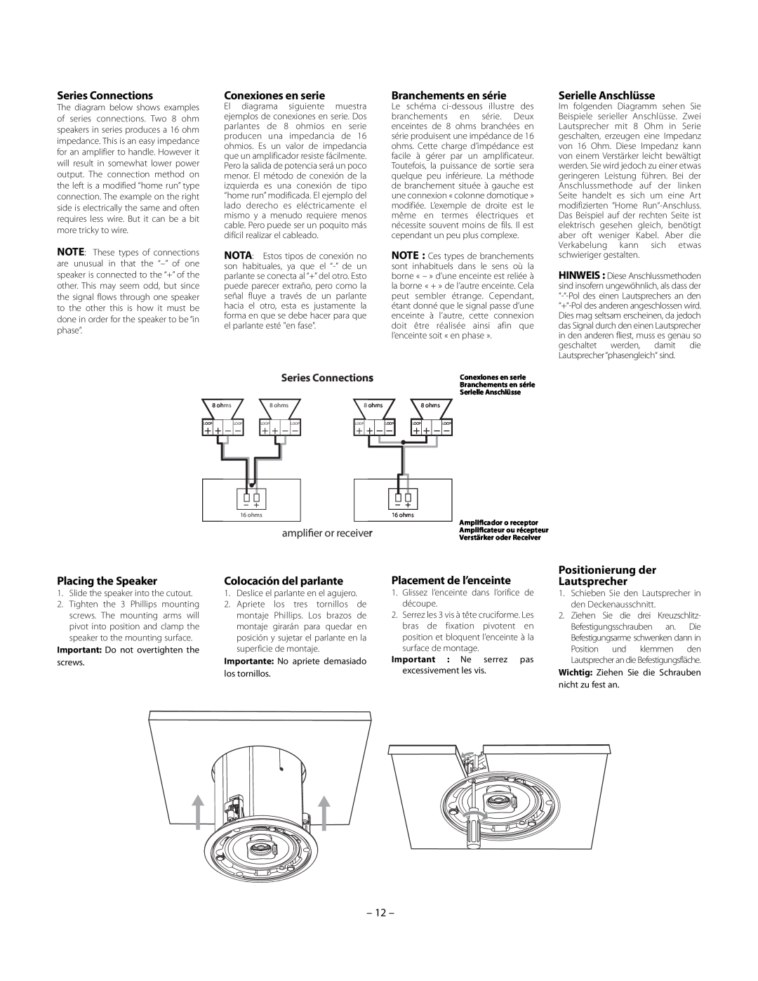
The diagram below shows examples of series connections. Two 8 ohm speakers in series produces a 16 ohm impedance. This is an easy impedance for an amplifier to handle. However it will result in somewhat lower power output. The connection method on the left is a modified “home run” type connection. The example on the right side is electrically the same and often requires less wire. But it can be a bit more tricky to wire.
NOTE: These types of connections are unusual in that the
Conexiones en serie
El diagrama siguiente muestra ejemplos de conexiones en serie. Dos parlantes de 8 ohmios en serie producen una impedancia de 16 ohmios. Es un valor de impedancia que un amplificador resiste fácilmente. Pero la salida de potencia será un poco menor. El método de conexión de la izquierda es una conexión de tipo “home run” modificada. El ejemplo del lado derecho es eléctricamente el mismo y a menudo requiere menos cable. Pero puede ser un poquito más difícil realizar el cableado.
NOTA: Estos tipos de conexión no son habituales, ya que el
Branchements en série
Le schéma
NOTE : Ces types de branchements sont inhabituels dans le sens où la borne « – » d’une enceinte est reliée à la borne « + » de l’autre enceinte. Cela peut sembler étrange. Cependant, étant donné que le signal passe d’une enceinte à l’autre, cette connexion doit être réalisée ainsi afin que l’enceinte soit « en phase ».
Serielle Anschlüsse
Im folgenden Diagramm sehen Sie Beispiele serieller Anschlüsse. Zwei Lautsprecher mit 8 Ohm in Serie geschalten, erzeugen eine Impedanz von 16 Ohm. Diese Impedanz kann von einem Verstärker leicht bewältigt werden. Sie wird jedoch zu einer etwas geringeren Leistung führen. Bei der Anschlussmethode auf der linken Seite handelt es sich um eine Art modifizierten “Home
HINWEIS : Diese Anschlussmethoden sind insofern ungewöhnlich, als dass der
|
|
|
|
|
|
|
|
|
|
|
|
|
|
|
|
|
|
|
|
|
|
|
|
|
| Series Connections |
|
|
|
|
|
|
|
|
|
|
|
|
|
|
|
|
| Conexiones en serie | |||||||||||||||||||
|
|
|
|
|
|
|
|
|
|
|
|
|
|
|
|
|
|
|
|
|
|
|
|
|
|
|
|
|
|
|
|
|
|
|
|
|
|
|
|
|
|
|
|
|
|
|
|
|
|
|
|
|
|
|
|
|
|
|
|
|
|
| Branchements en série |
|
|
|
|
|
|
|
|
|
|
|
|
|
|
|
|
|
|
|
|
|
|
|
|
|
|
|
|
|
|
|
|
|
|
|
|
|
|
|
|
|
|
|
|
|
|
|
|
|
|
|
|
|
|
|
|
|
|
|
|
|
|
| Serielle Anschlüsse |
|
|
|
|
|
| 8 ohms |
|
|
|
|
|
| 8 ohms |
|
|
|
|
| 8 ohms |
|
|
|
|
|
|
|
|
| 8 ohms | ||||||||||||||||||||||||||||||||||
| LOOP |
|
|
|
|
|
|
|
| LOOP |
| LOOP |
|
|
|
|
|
|
| LOOP |
| LOOP |
|
|
|
|
|
|
|
|
| LOOP |
|
| LOOP |
|
|
|
|
|
| LOOP |
| ||||||||||||||||||||
|
|
|
|
|
|
|
|
|
|
|
|
|
|
|
|
|
|
|
|
|
|
|
|
|
|
|
|
|
|
|
|
|
|
|
| ||||||||||||||||||||||||||||
|
|
|
|
|
|
|
|
|
|
|
|
|
|
|
|
|
|
|
|
|
|
|
|
|
|
|
|
|
|
|
|
|
|
|
|
|
|
|
|
|
|
|
|
|
|
|
|
|
|
|
|
|
|
|
|
|
|
|
|
|
|
|
|
|
|
|
|
|
|
|
|
|
|
|
|
|
|
|
|
|
|
|
|
|
|
|
|
|
|
|
|
|
|
|
|
|
|
|
|
|
|
|
|
|
|
|
|
|
|
|
|
|
|
|
|
|
|
|
|
|
|
|
|
|
|
|
|
|
|
|
|
|
|
|
|
|
|
|
|
|
|
|
|
|
|
|
|
|
|
|
|
|
|
|
|
|
|
|
|
|
|
|
|
|
|
|
|
|
|
|
|
|
|
|
|
|
|
|
|
|
|
|
|
|
|
|
|
|
|
|
|
|
|
|
|
|
|
|
|
|
|
|
|
|
|
|
|
|
|
|
|
|
|
|
|
|
|
|
|
|
|
|
|
|
|
|
|
|
|
|
|
|
|
|
|
|
|
|
|
|
|
|
|
|
|
|
|
|
|
|
|
|
|
|
|
|
|
|
|
|
| 16 ohms |
|
|
| 16 ohms | |||||||||||||||
|
|
|
|
|
|
|
|
|
|
|
|
|
|
|
|
|
|
|
|
|
|
amplifier or receiver
Amplificador o receptor Amplificateur ou récepteur Verstärker oder Receiver
Placing the Speaker
1.Slide the speaker into the cutout.
2.Tighten the 3 Phillips mounting screws. The mounting arms will pivot into position and clamp the speaker to the mounting surface.
Important: Do not overtighten the screws.
Colocación del parlante
1.Deslice el parlante en el agujero.
2.Apriete los tres tornillos de montaje Phillips. Los brazos de montaje girarán para quedar en posición y sujetar el parlante en la superficie de montaje.
Importante: No apriete demasiado los tornillos.
Placement de l’enceinte
1.Glissez l’enceinte dans l’orifice de découpe.
2.Serrez les 3 vis à tête cruciforme. Les bras de fixation pivotent en position et bloquent l’enceinte à la surface de montage.
Important : Ne serrez pas excessivement les vis.
Positionierung der
Lautsprecher
1.Schieben Sie den Lautsprecher in den Deckenausschnitt.
2.Ziehen Sie die drei Kreuzschlitz- Befestigungsschrauben an. Die Befestigungsarme schwenken dann in Position und klemmen den Lautsprecher an die Befestigungsfläche.
Wichtig: Ziehen Sie die Schrauben nicht zu fest an.