The Bradford


 White
White

 DEFENDER
Safety System®
SERVICE PROCEDURE
Gas Control
Testing, Disassembly & Replacement (Honeywell)
GAS CONTROL DISASSEMBLY/REASSEMBLY
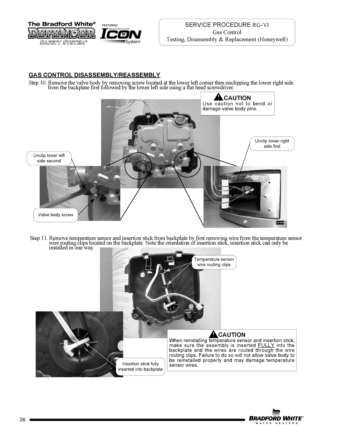
Step 10. Remove the valve body by removing screw located at the lower left corner then unclipping the lower right side from the backplate first followed by the lower left side using a flat head screwdriver.
CAUTION
Use caution not to bend or damage valve body pins.
Unclip lower right
side first
Unclip lower left
side second
Valve body screw
Step 11. Remove temperature sensor and insertion stick from backplate by first removing wire from the temperature sensor wire routing clips located on the backplate. Note the orientation of insertion stick, insertion stick can only be installed in one way.
Temperature sensor
wire routing clips
Insertion stick fully
inserted into backplate
CAUTION
When reinstalling temperature sensor and insertion stick, make sure the assembly is inserted FULLY into the backplate and the wires are routed through the wire routing clips. Failure to do so will not allow valve body to be reinstalled properly and may damage temperature sensor wires.
26
26