Installation, cont’d
Wiring the Power Connector
If using a different external power supply from the one provided with the SW2/SW4, you may need to wire the connector for it.
To wire the power connector,
1. Cut the DC output cord to the length needed.
2. Strip the jacket to expose 3/16" (5 mm) of the conductors.
CExposing more than 3/16” (5 mm) of the copper wires could allow the stripped wires to touch each other, causing a short circuit. This could result in the external DC power supply overheating and/or burning.
Stripping the wires to expose less than the recommended amount may cause them to slide out of the connector too easily, even if they are tightly pinched by the captive screws.
3. Slide the leads into the supplied
4. To verify the power cord’s polarity before connecting it, plug in the power supply with no load and check the output with a voltmeter.
5. Use the supplied
The figure below shows how to wire the connector.
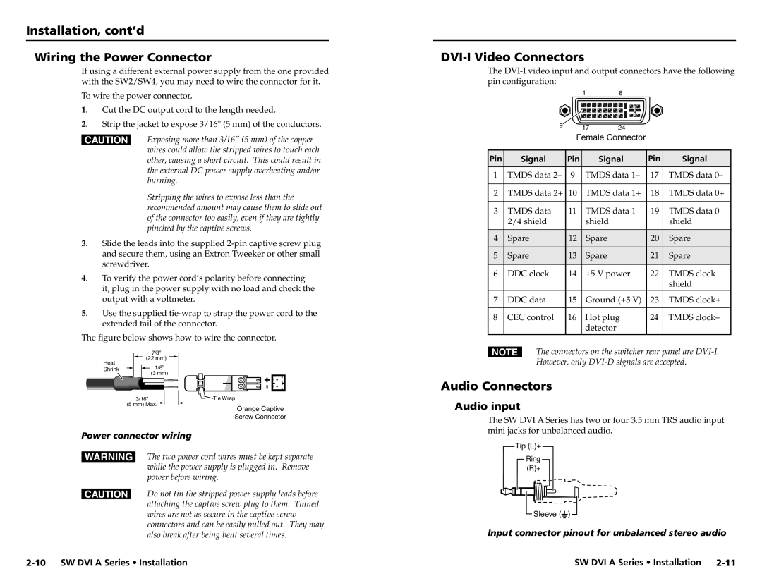
DVI-I Video Connectors
The
18
| 9 |
| 17 | 24 |
|
|
|
|
|
|
| ||
|
| Female Connector |
|
| ||
|
|
|
|
|
| |
Pin | Signal | Pin | Signal | Pin | Signal | |
1 | TMDS data 2– | 9 | TMDS data 1– | 17 | TMDS data 0– | |
|
|
|
|
|
| |
2 | TMDS data 2+ | 10 | TMDS data 1+ | 18 | TMDS data 0+ | |
|
|
|
|
|
| |
3 | TMDS data | 11 | TMDS data 1 | 19 | TMDS data 0 | |
| 2/4 shield |
| shield |
|
| shield |
|
|
|
|
|
|
|
4 | Spare | 12 | Spare |
| 20 | Spare |
|
|
|
|
|
|
|
5 | Spare | 13 | Spare |
| 21 | Spare |
|
|
|
|
|
| |
6 | DDC clock | 14 | +5 V power | 22 | TMDS clock | |
|
|
|
|
|
| shield |
|
|
|
|
|
| |
7 | DDC data | 15 | Ground (+5 V) | 23 | TMDS clock+ | |
|
|
|
|
|
| |
8 | CEC control | 16 | Hot plug | 24 | TMDS clock– | |
|
|
| detector |
|
|
|
|
|
|
|
|
|
|
Heat
7/8”
(22 mm) ![]()
N The connectors on the switcher rear panel are |
However, only |
Shrink ![]()
![]() 1/8” (3 mm)
1/8” (3 mm)
3/16” | Tie Wrap |
(5 mm) Max. | Orange Captive |
| |
| Screw Connector |
Power connector wiring
WThe two power cord wires must be kept separate while the power supply is plugged in. Remove power before wiring.
CDo not tin the stripped power supply leads before attaching the captive screw plug to them. Tinned wires are not as secure in the captive screw connectors and can be easily pulled out. They may also break after being bent several times.
Audio Connectors
Audio input
The SW DVI A Series has two or four 3.5 mm TRS audio input mini jacks for unbalanced audio.
Tip (L)+
Ring
(R)+
![]() Sleeve (
Sleeve (![]() )
) ![]()
Input connector pinout for unbalanced stereo audio
SW DVI A Series • Installation |