SIS Configuration and Control
The SW2/SW4 can be remotely set up and controlled via a host computer or other device (such as a control system), attached to the rear panel
Host-to-Switcher Communications
SIS commands consist of one or more characters per field. No special characters are required to begin or end a command sequence. You can enter these commands from your computer using a communication software program such as HyperTerminal. When the switcher determines that a command is valid, it executes the command and sends a response to the host device.
Most responses from the SW2/SW4 to the host computer end with a carriage return and a line feed (CR/LF = ]), which signals the end of the response character string. A string is one or more characters.
Switcher-initiated messages
When a local event such as a front panel selection takes place, the switcher responds by sending a message to the host, indicating what selection was entered. No response is required from the host. The following
(C)Copyright 2007, Extron Electronics DVI Switcher Series, Vx.xx,
The switcher sends the copyright message when it first powers on. Vx.xx is the firmware version number.
NThis message is displayed only at
Error responses
If the switcher is unable to execute a command it receives because the command is invalid or contains invalid parameters, the SW2/SW4 returns an error response to the host. Error response codes and their descriptions are as follows:
E01 – Invalid input channel number (out of range)
E06 – Invalid input selection during autoswitch
E10 – Invalid command
E13 – Invalid value (out of range)
Using the Command/Response Table
The command/response table on the following pages lists valid ASCII and hexadecimal command codes, the switcher’s responses to the host, and a description of the command’s function or the results of executing the command.
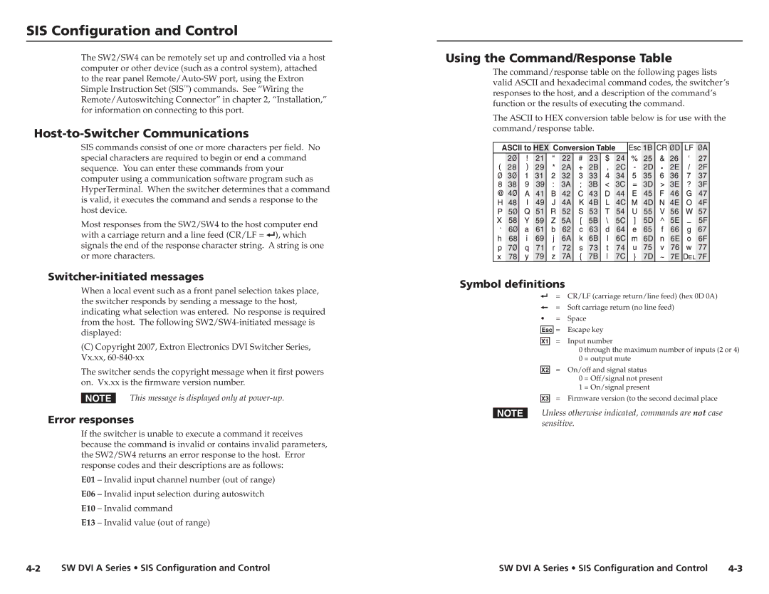
The ASCII to HEX conversion table below is for use with the command/response table.
ASCII to HEX Conversion Table |
• |
Symbol definitions
] = CR/LF (carriage return/line feed) (hex 0D 0A)
}= Soft carriage return (no line feed)
• = Space E= Escape key
X! | = | Input number | |
|
| 0 through the maximum number of inputs (2 or 4) | |
|
| 0 | = output mute |
X@ | = | On/off and signal status | |
|
| 0 | = Off/signal not present |
|
| 1 | = On/signal present |
X# | = | Firmware version (to the second decimal place | |
NUnless otherwise indicated, commands are not case sensitive.
SW DVI A Series • SIS Configuration and Control | SW DVI A Series • SIS Configuration and Control |