Installation, cont’d
Audio output
The
Tip | L | Tip | L | |
NO GROUND HERE | Ring | |||
|
| |||
Sleeves |
| Sleeves |
| |
Tip | R | Tip | R | |
NO GROUND HERE | Ring | |||
|
| |||
Unbalanced Output |
|
| Balanced Output |
C
For unbalanced audio, connect both sleeves
to the center contact ground. DO NOT connect the sleeves to the negative
Do not tin the wires!
Wiring the audio output connector
Wiring the Remote/Autoswitching Connector
The
Wiring for RS-232
1. Wire the
a. Connect the red wire to the first pin on the left, which plugs into the Tx (transmit) port.
b. Connect the orange wire to the second pin, which plugs into the Rx (receive) port.
c. Connect the green wire to the third pin, which plugs into the ground port, marked with this symbol: _
2. Plug the
The following figure shows how to wire this shared connector for
TxRx  A S SW 2 or SW 4 DVI A Switcher
Rear Ranel
RS-232 Port
Connect a ground wire between the switcher and the computer or control system.
Green |
|
|
| Ground |
|
| |
Orange | Rx |
| Transmit (Tx) 3 | ||||
Receive |
|
| |||||
Red |
|
| |||||
Tx | Transmit |
| Receive (Rx) 2 | ||||
To connect your computer or control system to the
If you use cable that has a drain wire, tie the drain wire to ground at both ends.
9 pin HD
Connector
To Computer or
Control System
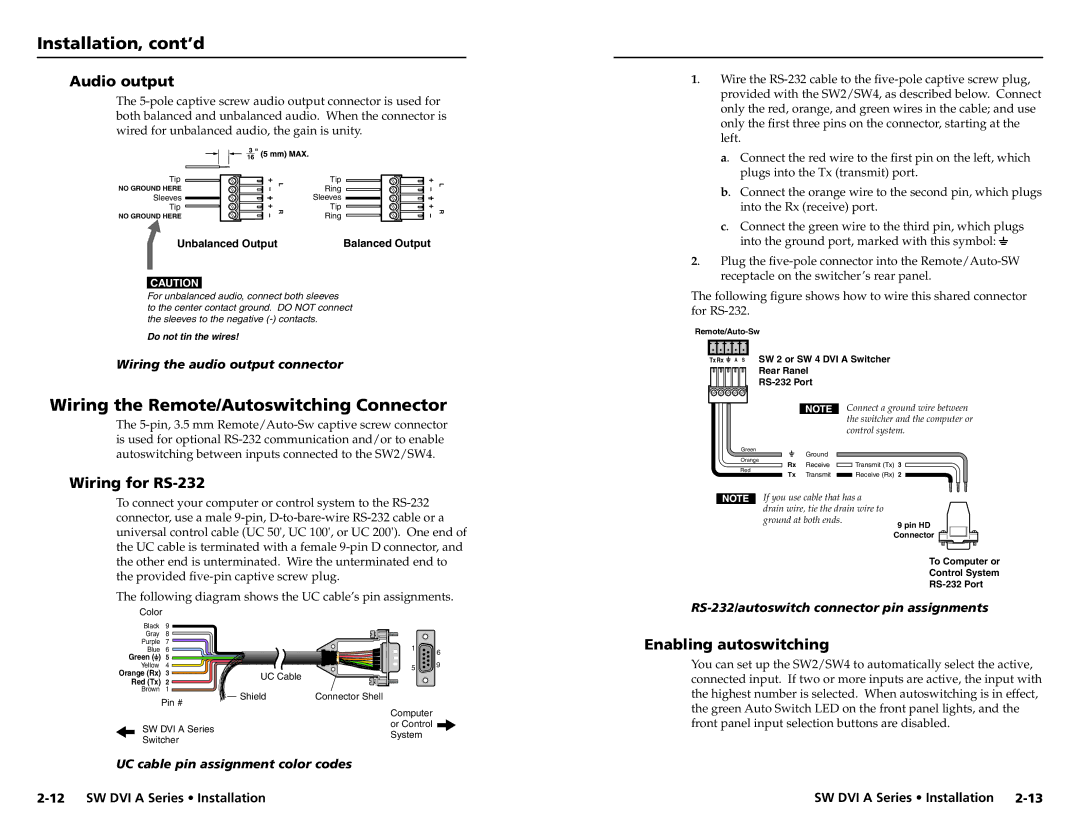
The following diagram shows the UC cable’s pin assignments.
Color
Black | 9 |
|
|
|
Gray | 8 |
|
|
|
Purple | 7 |
| 1 |
|
Blue | 6 |
| 6 | |
Green ( ) | 5 |
|
| |
|
| 9 | ||
Yellow | 4 |
| 5 | |
Orange (Rx) | 3 | UC Cable |
| |
|
| |||
Red (Tx) | 2 |
|
| |
|
|
| ||
Brown | 1 | Shield | Connector Shell |
|
| Pin # |
| ||
|
|
|
|
| Computer | |
SW DVI A Series | or Control | |
System | ||
Switcher | ||
|
UC cable pin assignment color codes
Enabling autoswitching
You can set up the SW2/SW4 to automatically select the active, connected input. If two or more inputs are active, the input with the highest number is selected. When autoswitching is in effect, the green Auto Switch LED on the front panel lights, and the front panel input selection buttons are disabled.
SW DVI A Series • Installation