Honeywell Gas Control Troubleshooting Chart
Flammable Vapor Ignition Resistant Water Heaters
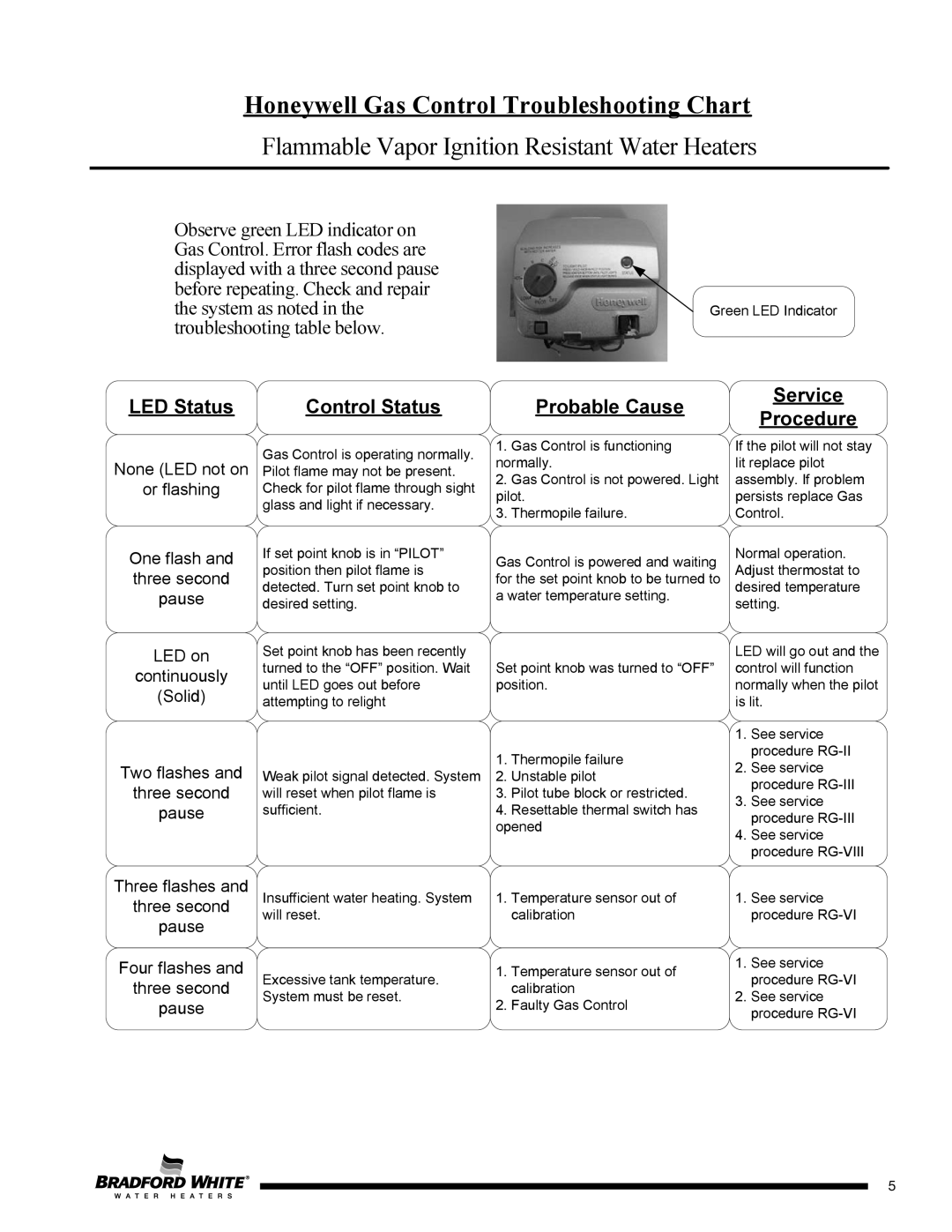
Observe green LED indicator on Gas Control. Error flash codes are displayed with a three second pause before repeating. Check and repair the system as noted in the troubleshooting table below.
Green LED Indicator
LED Status | Control Status | |
|
|
|
Probable Cause
Service
Procedure
None (LED not on
or flashing
One flash and three second pause
LED on
continuously
(Solid)
Two flashes and
three second
pause
Gas Control is operating normally. Pilot flame may not be present. Check for pilot flame through sight glass and light if necessary.
If set point knob is in “PILOT” position then pilot flame is detected. Turn set point knob to desired setting.
Set point knob has been recently turned to the “OFF” position. Wait until LED goes out before attempting to relight
Weak pilot signal detected. System will reset when pilot flame is sufficient.
1. Gas Control is functioning normally.
2. Gas Control is not powered. Light pilot.
3. Thermopile failure.
Gas Control is powered and waiting for the set point knob to be turned to a water temperature setting.
Set point knob was turned to “OFF” position.
1. Thermopile failure
2. Unstable pilot
3. Pilot tube block or restricted.
4. Resettable thermal switch has opened
If the pilot will not stay lit replace pilot assembly. If problem persists replace Gas Control.
Normal operation. Adjust thermostat to desired temperature setting.
LED will go out and the control will function normally when the pilot is lit.
1.See service procedure
2.See service procedure
3.See service procedure
4.See service procedure
Three flashes and | Insufficient water heating. System | |
three second | will reset. | |
pause | ||
| ||
Four flashes and | Excessive tank temperature. | |
three second | ||
System must be reset. | ||
pause | ||
|
1.Temperature sensor out of calibration
1.Temperature sensor out of calibration
2.Faulty Gas Control
1.See service procedure
1.See service procedure
2.See service procedure
5
5
