WARNING! DO NOT USE 2” VENT WITH EF100T250/300 MODELS
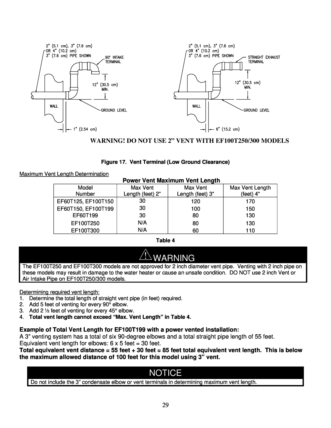
Figure 17. Vent Terminal (Low Ground Clearance)
Maximum Vent Length Determination
Power Vent Maximum Vent Length
Model | Max Vent | Max Vent | Max Vent Length |
Number | Length (feet) 2” | Length (feet) 3" | (feet) 4" |
EF60T125, EF100T150 | 30 | 120 | 170 |
EF60T150, EF100T199 | 30 | 100 | 150 |
EF60T199 | 30 | 80 | 130 |
EF100T250 | N/A | 80 | 130 |
EF100T300 | N/A | 60 | 110 |
Table 4
![]() WARNING
WARNING
The EF100T250 and EF100T300 models are not approved for 2 inch diameter vent pipe. Venting with 2 inch pipe on these models may result in damage to the water heater or cause an unsafe condition. DO NOT use 2 inch Vent or Air Intake Pipe on EF100T250/300 models.
Determining required vent length:
1.Determine the total length of straight vent pipe (in feet) required.
2.Add 5 feet of venting for every 90° elbow.
3.Add 2 ½ feet of venting for every 45° elbow.
4.Total vent length cannot exceed “Max. Vent Length” in Table 4.
Example of Total Vent Length for EF100T199 with a power vented installation:
A 3” venting system has a total of six
Total equivalent vent distance = 55 feet + 30 feet = 85 feet total equivalent vent length. This is below the maximum allowed distance of 100 feet for this model using 3” vent.
NOTICE
Do not include the 3” condensate elbow or vent terminals in determining maximum vent length.
29