9.Operate heater through one cycle to ensure
Horizontal Installation:
1.Become familiar with coaxial vent kit part no.
![]() WARNING
WARNING
The EF100T250 and EF100T300 models are not approved for 2 inch diameter vent pipe. Venting with 2 inch pipe on these models may result in damage to the water heater or cause an unsafe condition. DO NOT use 2 inch Vent or Air Intake Pipe on EF100T250/300 models.
2.Determine the best location for the termination kit.
NOTICE
![]() Position termination where vent vapors will not damage plants/shrubs or air conditioning equipment.
Position termination where vent vapors will not damage plants/shrubs or air conditioning equipment.
![]() Position termination where vent vapors will not be adversely affected by wind condition.
Position termination where vent vapors will not be adversely affected by wind condition.
Position termination where it will not be damaged or be subjected to foreign objects.
Position termination where vapors will not be objectionable.
3.Cut the recommended 5” (12.7 cm) diameter hole (for 3” vent termination) or 4 inch (10.2 cm) for 2” vent termination kit.
4.Partially assemble vent kit.
a.Cement Y concentric fitting to larger diameter kit pipe. (See Figure 20).
b.Cement rain cap to smaller diameter kit pipe. (See Figure 21).
5.Install concentric Y fitting and pipe assembly through the structure’s hole and
6.Install rain cap and small diameter pipe assembly in concentric Y fitting and large pipe assembly. Ensure small diameter pipe is cemented and bottomed in concentric Y fitting.
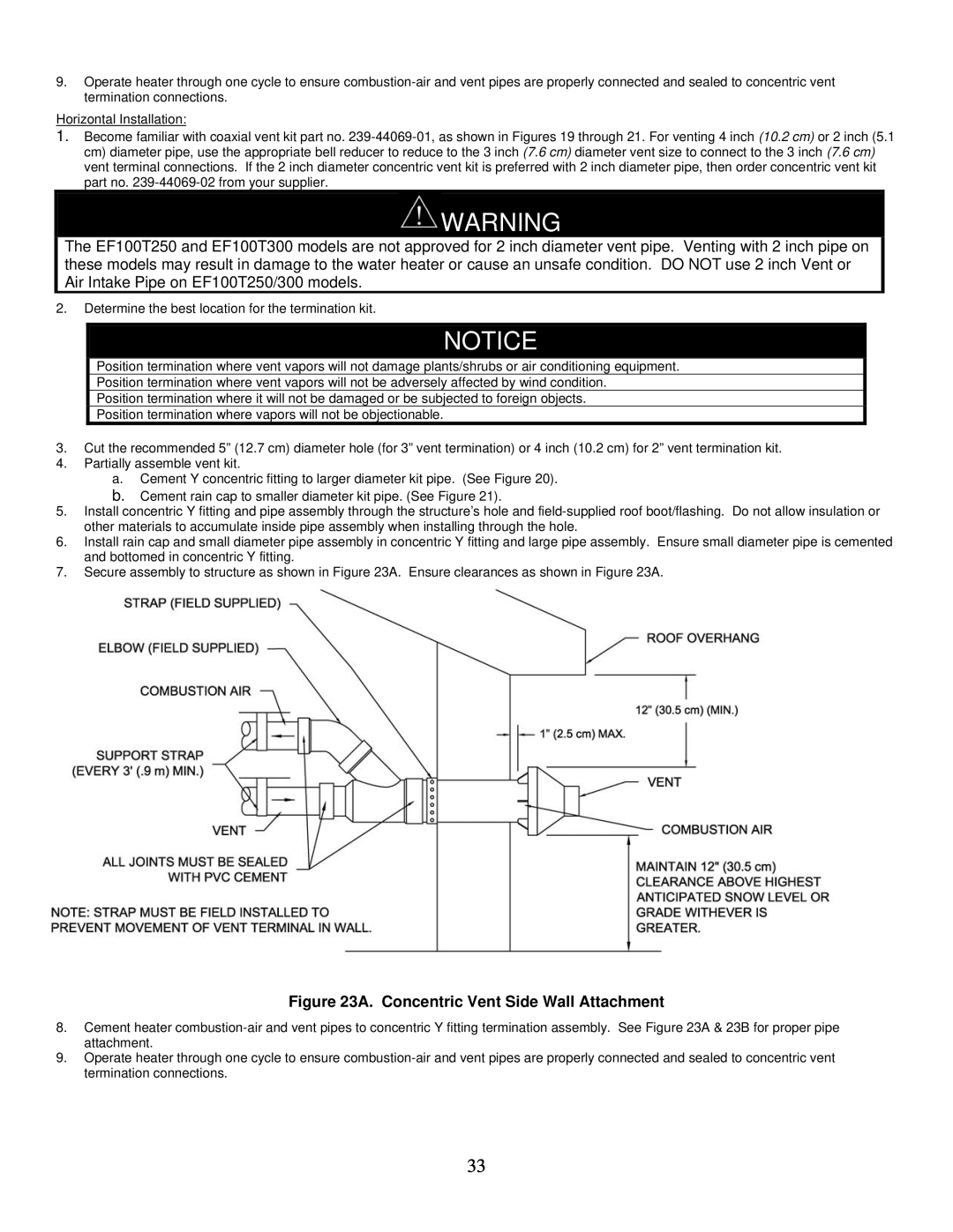
7.Secure assembly to structure as shown in Figure 23A. Ensure clearances as shown in Figure 23A.
Figure 23A. Concentric Vent Side Wall Attachment
8.Cement heater
9.Operate heater through one cycle to ensure
33