should extend below level of furnace gas controls. Place a ground joint union between furnace gas control valve and exterior manual equipment gas shutoff valve.
A
Piping should be pressure and leak tested in accordance with the current addition of the NFGC in the United States, local, and national plumbing and gas codes before the furnace has been connected. After all connections have been made, purge lines and check for leakage at furnace prior to operating furnace.
| If pressure exceeds 0.5 psig | |
| be disconnected from furnace and capped before and during | |
| supply pipe pressure test. If test pressure is equal to or less than | |
| 0.5 psig | |
| furnace gas control valve and accessible manual equipment | |
315AAV | ||
shutoff valve before and during supply pipe pressure test. After | ||
all connections have been made, purge lines and check for | ||
| ||
| leakage at furnace prior to operating furnace. | |
| The gas supply pressure shall be within the maximum and | |
| minimum inlet supply pressures marked on the rating plate with | |
| the furnace burners ON and OFF. |
2” (51mm)
Street Elbow
A08551
Fig. 21 - Burner and Manifold
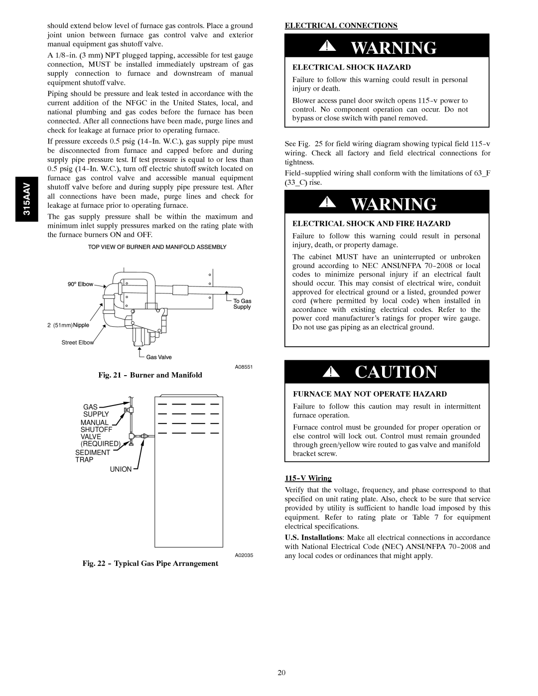
GAS![]()
![]()
SUPPLY
MANUAL
SHUTOFF
VALVE ![]()
![]()
![]()
![]() (REQUIRED)
(REQUIRED) ![]()
![]()
![]()
![]()
SEDIMENT TRAP
UNION
A02035
Fig. 22 - Typical Gas Pipe Arrangement
ELECTRICAL CONNECTIONS
!WARNING
ELECTRICAL SHOCK HAZARD
Failure to follow this warning could result in personal injury or death.
Blower access panel door switch opens
See Fig. 25 for field wiring diagram showing typical field
!WARNING
ELECTRICAL SHOCK AND FIRE HAZARD
Failure to follow this warning could result in personal injury, death, or property damage.
The cabinet MUST have an uninterrupted or unbroken ground according to NEC ANSI/NFPA
!CAUTION
FURNACE MAY NOT OPERATE HAZARD
Failure to follow this caution may result in intermittent furnace operation.
Furnace control must be grounded for proper operation or else control will lock out. Control must remain grounded through green/yellow wire routed to gas valve and manifold bracket screw.
115-V Wiring
Verify that the voltage, frequency, and phase correspond to that specified on unit rating plate. Also, check to be sure that service provided by utility is sufficient to handle load imposed by this equipment. Refer to rating plate or Table 7 for equipment electrical specifications.
U.S. Installations: Make all electrical connections in accordance with National Electrical Code (NEC) ANSI/NFPA
20