Bryant 315AAV instruction manual

Models: 315AAV

1 60
Download 60 pages 15.94 Kb
Page 39
Image 39
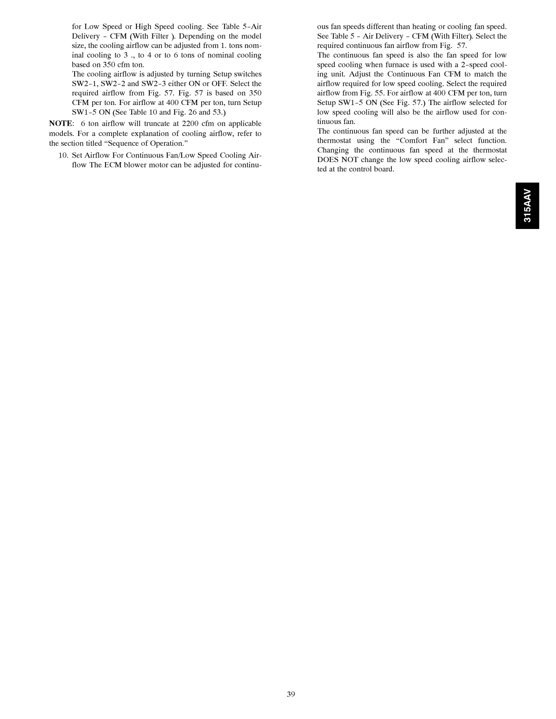
for Low Speed or High Speed cooling. See Table 5-Air Delivery - CFM (With Filter ). Depending on the model size, the cooling airflow can be adjusted from 1. tons nom- inal cooling to 3 ., to 4 or to 6 tons of nominal cooling based on 350 cfm ton.

for Low Speed or High Speed cooling. See Table 5-Air Delivery - CFM (With Filter ). Depending on the model size, the cooling airflow can be adjusted from 1. tons nom- inal cooling to 3 ., to 4 or to 6 tons of nominal cooling based on 350 cfm ton.

The cooling airflow is adjusted by turning Setup switches SW2-1, SW2-2 and SW2-3 either ON or OFF. Select the required airflow from Fig. 57. Fig. 57 is based on 350 CFM per ton. For airflow at 400 CFM per ton, turn Setup SW1-5 ON (See Table 10 and Fig. 26 and 53.)

NOTE: 6 ton airflow will truncate at 2200 cfm on applicable models. For a complete explanation of cooling airflow, refer to the section titled “Sequence of Operation.”

10.Set Airflow For Continuous Fan/Low Speed Cooling Air- flow The ECM blower motor can be adjusted for continu-

ous fan speeds different than heating or cooling fan speed. See Table 5 - Air Delivery - CFM (With Filter). Select the required continuous fan airflow from Fig. 57.

The continuous fan speed is also the fan speed for low speed cooling when furnace is used with a 2-speed cool- ing unit. Adjust the Continuous Fan CFM to match the airflow required for low speed cooling. Select the required airflow from Fig. 55. For airflow at 400 CFM per ton, turn Setup SW1-5 ON (See Fig. 57.) The airflow selected for low speed cooling will also be the airflow used for con- tinuous fan.

The continuous fan speed can be further adjusted at the thermostat using the “Comfort Fan” select function. Changing the continuous fan speed at the thermostat DOES NOT change the low speed cooling airflow selec- ted at the control board.

315AAV

39
Page 39
Image 39
Bryant 315AAV instruction manual