315AAV
Table 10 – Furnace Setup Switch Description
SETUP SWITCH | SWITCH NAME | NORMAL | DESCRIPTION OF USE | |
NO. | POSITION | |||
|
| |||
Status Code Recovery | OFF | Turn ON to retrieve up to 7 stored status codes for troubleshooting as- | ||
sistance when R thermostat lead is disconnected. | ||||
|
|
| ||
|
|
|
| |
|
|
| Allows | |
Adaptive Heat Mode | OFF | using 2 stage thermostat to allow Low Heat operation when R to W/W1 | ||
|
|
| closes and High Heat operation when R to W/W1 and W2 close. | |
|
|
|
| |
Low Heat Rise Adjust | OFF | Turn ON to increase Low Heat airflow by 18 percent. This compensates | ||
for increased return air temperature caused with bypass humidifier. | ||||
|
|
| ||
Comfort/Efficiency Ad- | ON | Turn ON to decrease Low Heat airflow by 16 percent and High Heat | ||
justment | airflow 10 percent for maximum comfort. | |||
|
| |||
CFM per ton adjust | OFF | Turn ON for 400 CFM per ton. Turn OFF for 350 CFM per ton. | ||
|
|
| Turn ON to initiate Component | |
Component | OFF | when R thermostat lead is disconnected. Turn OFF when | ||
|
|
| completed. | |
|
|
|
| |
Blower OFF delay | ON or OFF | Control blower Off Delay time. Used in conjunction with | ||
Table 11. | ||||
|
|
| ||
Blower OFF delay | ON or OFF | Control blower Off Delay time. Used in conjunction with | ||
Table 11. | ||||
|
|
| ||
|
|
|
|
|
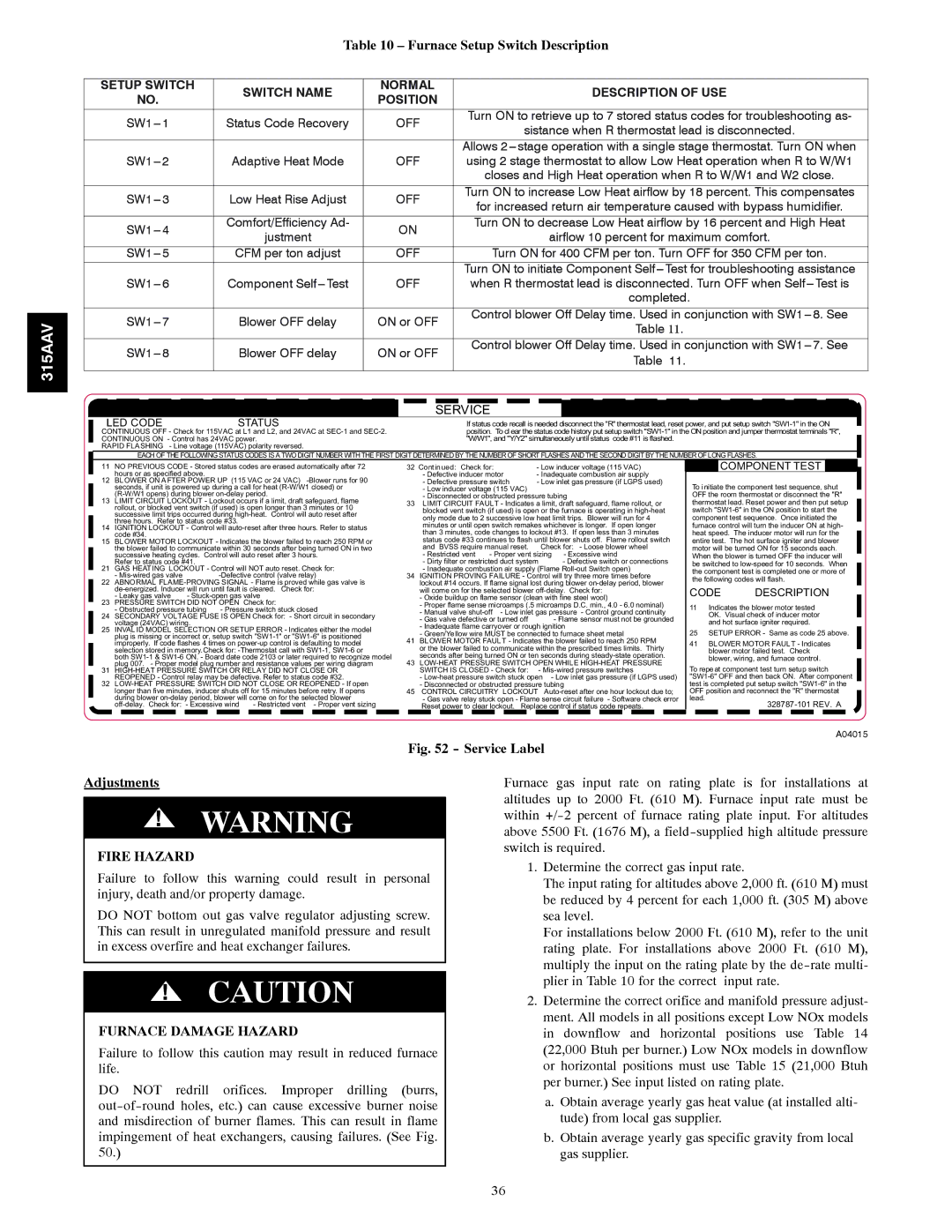
| SERVICE |
LED CODE | STATUS | If status code recall is needed disconnect the "R" thermostat lead, reset power, and put setup switch |
CONTINUOUS OFF - Check for 115VAC at L1 and L2, and 24VAC at | position. To clear the status code history put setup switch | |
CONTINUOUS ON - Control has 24VAC power. | "W/W1", and "Y/Y2" simultaneously until status code #11 is flashed. | |
RAPID FLASHING - Line voltage (115VAC) polarity reversed.
| EACH OF THE FOLLOWING STATUS CODES ISA TWO DIGIT NUMBER WITH THE FIRST DIGIT DETERMINED BY THE NUMBER OF SHORT FLASHES AND THE SECOND DIGIT BY THE NUMBER OF LONG FLASHES. | |||||||||||||
11 | NO PREVIOUS CODE - Stored status codes are erased automatically after 72 | 32 Continued: Check for: |
| - Low inducer voltage (115 VAC) |
| COMPONENT TEST |
| |||||||
12 | hours or as specified above. |
|
| - Defective inducer motor | - Inadequate combustion air supply |
|
|
|
| |||||
BLOWER ON AFTER POWER UP (115 VAC or 24 VAC) |
| - Defective pressure switch | - Low inlet gas pressure (if LGPS used) | To initiate the component test sequence, shut | ||||||||||
| seconds, if unit is powered up during a call for heat |
| - Low inducer voltage (115 VAC) |
|
| |||||||||
13 |
|
| - Disconnected or obstructed pressure tubing | OFF the room thermostat or disconnect the "R" | ||||||||||
LIMIT CIRCUIT LOCKOUT - Lockout occurs if a limit, draft safeguard, flame | 33 LIMIT CIRCUIT FAULT - Indicates a limit, draft safeguard, flame rollout, or | thermostat lead. Reset power and then put setup | ||||||||||||
| rollout, or blocked vent switch (if used) is open longer than 3 minutes or 10 |
| blocked vent switch (if used) is open or the furnace is operating in | switch | ||||||||||
| successive limit trips occurred during |
| ||||||||||||
|
| only mode due to 2 successive low heat limit trips. Blower will run for 4 | component test sequence. Once initiated the | |||||||||||
| three hours. Refer to status code #33. |
|
| |||||||||||
|
|
| minutes or until open switch remakes whichever is longer. If open longer | furnace control will turn the inducer ON at high- | ||||||||||
14 | IGNITION LOCKOUT - Control will |
| ||||||||||||
| than 3 minutes, code changes to lockout #13. If open less than 3 minutes | heat speed. The inducer motor will run for the | ||||||||||||
15 | code #34. |
|
|
|
| |||||||||
BLOWER MOTOR LOCKOUT - Indicates the blower failed to reach 250 RPM or |
| status code #33 continues to flash until blower shuts off. Flame rollout switch | entire test. The hot surface igniter and blower | |||||||||||
| the blower failed to communicate within 30 seconds after being turned ON in two |
| and BVSS require manual reset. | Check for: - Loose blower wheel | motor will be turned ON for 15 seconds each. | |||||||||
| successive heating cycles. Control will auto reset after 3 hours. |
| - Restricted vent | - Proper vent sizing - Excessive wind | When the blower is turned OFF the inducer will | |||||||||
21 | Refer to status code #41. |
|
|
| - Dirty filter or restricted duct system | - Defective switch or connections | be switched to | |||||||
GAS HEATING LOCKOUT - Control will NOT auto reset. Check for: |
| - Inadequate combustion air supply (Flame | the component test is completed one or more of | |||||||||||
| - |
| 34 IGNITION PROVING FAILURE - Control will try three more times before | |||||||||||
22 |
| the following codes will flash. | ||||||||||||
ABNORMAL |
| lockout #14 occurs. If flame signal lost during blower | ||||||||||||
|
| will come on for the selected blower | CODE | DESCRIPTION | ||||||||||
23 | - Leaky gas valve | - |
|
| - Oxide buildup on flame sensor (clean with fine steel wool) | |||||||||
PRESSURE SWITCH DID NOT OPEN Check for: |
|
| - Proper flame sense microamps (.5 microamps D.C. min., 4.0 - 6.0 nominal) | 11 Indicates the blower motor tested | ||||||||||
| - Obstructed pressure tubing | - Pressure switch stuck closed |
| - Manual valve | - Low inlet gas pressure - Control ground continuity | |||||||||
24 | SECONDARY VOLTAGE FUSE IS OPEN Check for: - Short circuit in secondary |
| OK. Visual check of inducer motor | |||||||||||
| - Gas valve defective or turned off |
| - Flame sensor must not be grounded | |||||||||||
| voltage (24VAC) wiring. |
|
|
|
| and hot surface igniter required. | ||||||||
|
|
|
| - Inadequate flame carryover or rough ignition | ||||||||||
25 | INVAL ID MODEL SELECTION OR SETUP ERROR - Indicates either the model |
| 25 SETUP ERROR - Same as code 25 above. | |||||||||||
| - Green/Yellow wire MUST be connected to furnace sheet metal | |||||||||||||
| plug is missing or incorrect or, setup switch |
| ||||||||||||
| 41 BLOWER MOTOR FAULT - Indicates the blower failed to reach 250 RPM | 41 BLOWER MOTOR FAULT - Indicates | ||||||||||||
| improperly. If code flashes 4 times on | |||||||||||||
| selection stored in memory.Check for: |
| or the blower failed to communicate within the prescribed times limits. Thirty | blower motor failed test. Check | ||||||||||
| both | 43 | seconds after being turned ON or ten seconds during | blower, wiring, and furnace control. | ||||||||||
31 | plug 007. - Proper model plug number and resistance values per wiring diagram | To repeat component test turn setup switch | ||||||||||||
|
| SWITCH IS CLOSED - Check for: | - | |||||||||||
32 | REOPENED - Control relay may be defective. Refer to status code #32. |
| - | - Low inlet gas pressure (if LGPS used) | ||||||||||
45 | - Disconnected or obstructed pressure tubing | test is completed put setup switch | ||||||||||||
| longer than five minutes, inducer shuts off for 15 minutes before retry. If opens | CONTROL CIRCUITRY | LOCKOUT | OFF position and reconnect the "R" thermostat | ||||||||||
| during blower |
| - Gas valve relay stuck open - Flame sense circuit failure - Software check error | lead. |
| |||||||||
| - Proper vent sizing |
| Reset power to clear lockout. Replace control if status code repeats. |
|
| |||||||||
A04015
Fig. 52 - Service Label
Adjustments
!WARNING
FIRE HAZARD
Failure to follow this warning could result in personal injury, death and/or property damage.
DO NOT bottom out gas valve regulator adjusting screw. This can result in unregulated manifold pressure and result in excess overfire and heat exchanger failures.
!CAUTION
FURNACE DAMAGE HAZARD
Failure to follow this caution may result in reduced furnace life.
DO NOT redrill orifices. Improper drilling (burrs,
Furnace gas input rate on rating plate is for installations at altitudes up to 2000 Ft. (610 M). Furnace input rate must be within
1.Determine the correct gas input rate.
The input rating for altitudes above 2,000 ft. (610 M) must be reduced by 4 percent for each 1,000 ft. (305 M) above sea level.
For installations below 2000 Ft. (610 M), refer to the unit rating plate. For installations above 2000 Ft. (610 M), multiply the input on the rating plate by the
2.Determine the correct orifice and manifold pressure adjust- ment. All models in all positions except Low NOx models in downflow and horizontal positions use Table 14 (22,000 Btuh per burner.) Low NOx models in downflow or horizontal positions must use Table 15 (21,000 Btuh per burner.) See input listed on rating plate.
a.Obtain average yearly gas heat value (at installed alti- tude) from local gas supplier.
b.Obtain average yearly gas specific gravity from local gas supplier.
36