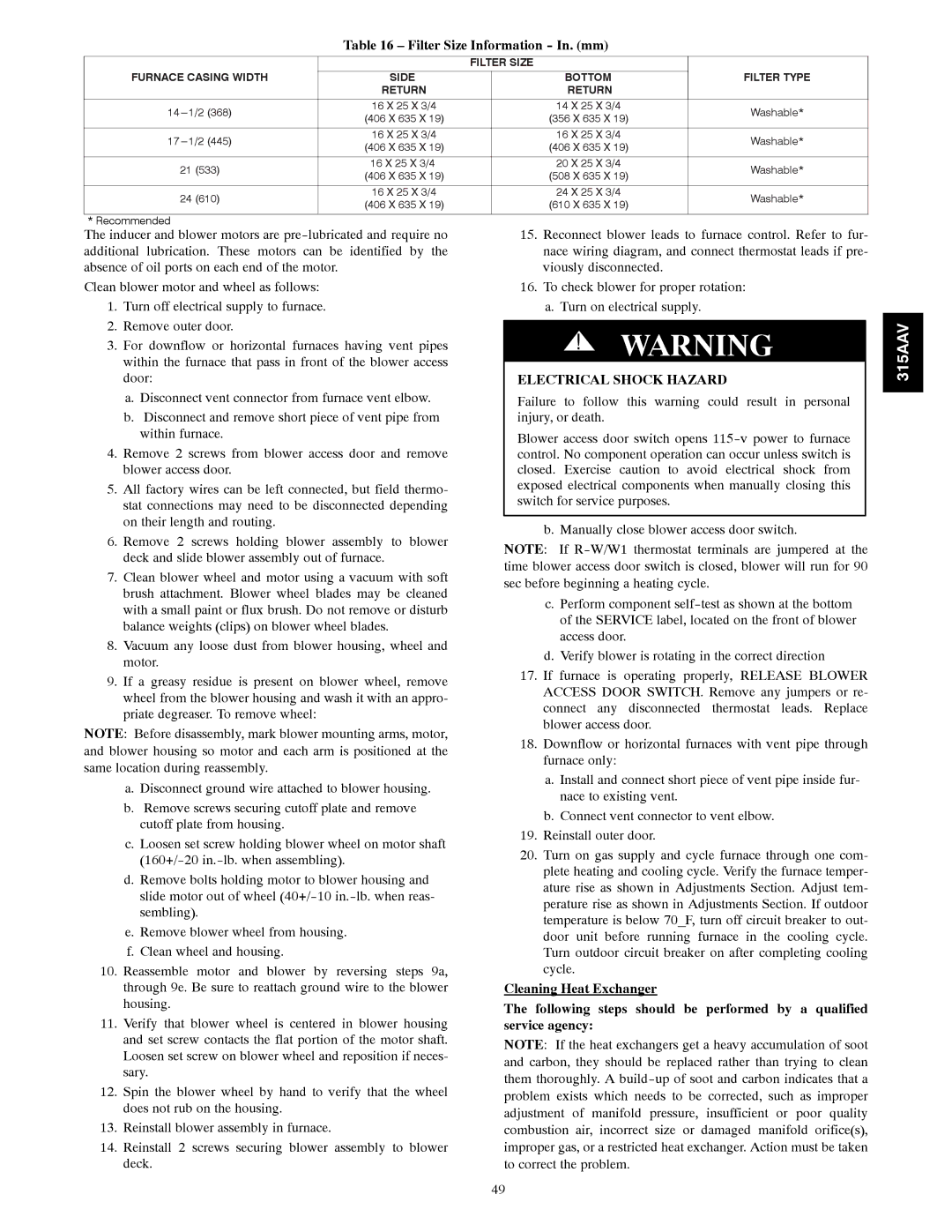
Table 16 – Filter Size Information - In. (mm)
|
|
| FILTER SIZE |
|
|
|
|
| |||
FURNACE CASING WIDTH |
| SIDE |
|
|
| BOTTOM |
|
| FILTER TYPE | ||
|
| RETURN |
|
|
| RETURN |
|
|
|
|
|
| 16 X 25 X 3/4 |
|
|
| 14 X 25 X 3/4 |
| Washable* | ||||
| (406 X 635 X 19) |
|
|
| (356 X 635 X 19) |
| |||||
|
|
|
|
|
|
|
|
| |||
|
|
|
|
|
|
|
|
|
|
| |
| 16 X 25 X 3/4 |
|
|
| 16 X 25 X 3/4 |
| Washable* | ||||
| (406 X 635 X 19) |
|
|
| (406 X 635 X 19) |
| |||||
|
|
|
|
|
|
|
|
| |||
|
|
|
|
|
|
|
|
|
|
| |
21 (533) |
| 16 X 25 X 3/4 |
|
|
| 20 X 25 X 3/4 |
| Washable* | |||
| (406 X 635 X 19) |
|
|
| (508 X 635 X 19) |
| |||||
|
|
|
|
|
|
|
|
| |||
|
|
|
|
|
|
|
|
|
|
| |
24 (610) |
| 16 X 25 X 3/4 |
|
|
| 24 X 25 X 3/4 |
| Washable* | |||
| (406 X 635 X 19) |
|
|
| (610 X 635 X 19) |
| |||||
|
|
|
|
|
|
|
|
| |||
|
|
|
|
|
|
|
|
|
|
|
|
* Recommended |
|
|
|
|
|
|
|
|
|
|
|
The inducer and blower motors are |
|
|
| 15. Reconnect blower leads to furnace control. Refer to fur- | |||||||
additional lubrication. These motors can be identified by the |
|
|
| nace wiring diagram, and connect thermostat leads if pre- | |||||||
absence of oil ports on each end of the motor. |
|
|
| viously disconnected. |
|
|
| ||||
Clean blower motor and wheel as follows: |
|
|
|
| 16. To check blower for proper rotation: | ||||||
1. Turn off electrical supply to furnace. |
|
|
|
| a. Turn on electrical supply. |
|
|
| |||
2. Remove outer door. |
|
|
|
|
|
|
|
|
|
| |
|
|
| ! | WARNING |
| ||||||
3. For downflow or horizontal furnaces having vent pipes |
|
| |||||||||
within the furnace that pass in front of the blower access |
|
|
|
|
|
|
|
|
| ||
|
|
|
|
|
|
|
|
| |||
door: |
|
|
|
|
|
|
|
| |||
|
|
|
| ELECTRICAL SHOCK HAZARD |
|
|
| ||||
a. Disconnect vent connector from furnace vent elbow. |
|
|
| Failure to follow this warning could result in personal |
|
| |||||
b. Disconnect and remove short piece of vent pipe from |
|
|
| injury, or death. |
|
|
|
|
| ||
within furnace. |
|
|
|
| Blower access door switch opens |
|
| ||||
4. Remove 2 screws from blower access door and remove |
|
|
|
|
| ||||||
|
|
| control. No component operation can occur unless switch is |
|
| ||||||
blower access door. |
|
|
|
| closed. Exercise caution to avoid electrical shock from |
|
| ||||
5. All factory wires can be left connected, but field thermo- |
|
|
| exposed electrical components when manually closing this |
|
| |||||
|
|
| switch for service purposes. |
|
|
| |||||
stat connections may need to be disconnected depending |
|
|
|
|
|
| |||||
|
|
|
|
|
|
|
|
| |||
on their length and routing. |
|
|
|
|
|
|
|
|
|
| |
|
|
|
| b. Manually close blower access door switch. | |||||||
6. Remove 2 screws holding blower | assembly to blower |
|
|
| |||||||
|
| NOTE: If | |||||||||
deck and slide blower assembly out of furnace. |
|
| |||||||||
|
| time blower access door switch is closed, blower will run for 90 | |||||||||
7. Clean blower wheel and motor using a vacuum with soft |
|
| |||||||||
|
| sec before beginning a heating cycle. |
|
|
| ||||||
brush attachment. Blower wheel blades may be cleaned |
|
|
|
|
| ||||||
|
|
| c. Perform component | ||||||||
with a small paint or flux brush. Do not remove or disturb |
|
|
| ||||||||
|
|
| of the SERVICE label, located on the front of blower | ||||||||
balance weights (clips) on blower wheel blades. |
|
|
| ||||||||
|
|
| access door. |
|
|
| |||||
8. Vacuum any loose dust from blower housing, wheel and |
|
|
|
|
|
| |||||
|
|
| d. Verify blower is rotating in the correct direction | ||||||||
motor. |
|
|
|
| |||||||
|
|
|
| 17. If furnace is | operating properly, RELEASE BLOWER | ||||||
9. If a greasy residue is present on blower wheel, remove |
|
|
| ||||||||
|
|
| ACCESS DOOR SWITCH. Remove any jumpers or re- | ||||||||
wheel from the blower housing and wash it with an appro- |
|
|
| ||||||||
|
|
| connect any | disconnected thermostat leads. Replace | |||||||
priate degreaser. To remove wheel: |
|
|
|
| |||||||
|
|
|
| blower access door. |
|
|
| ||||
NOTE: Before disassembly, mark blower mounting arms, motor, |
|
|
|
|
|
| |||||
|
|
| 18. Downflow or horizontal furnaces with vent pipe through | ||||||||
and blower housing so motor and each arm is positioned at the |
|
|
| ||||||||
|
|
| furnace only: |
|
|
|
|
| |||
same location during reassembly. |
|
|
|
|
|
|
|
|
| ||
|
|
|
| a. Install and connect short piece of vent pipe inside fur- | |||||||
a. Disconnect ground wire attached to blower housing. |
|
|
| ||||||||
|
|
| nace to existing vent. |
|
|
| |||||
b. Remove screws securing cutoff plate and remove |
|
|
|
|
|
| |||||
|
|
| b. Connect vent connector to vent elbow. | ||||||||
cutoff plate from housing. |
|
|
|
| |||||||
|
|
|
| 19. Reinstall outer door. |
|
|
| ||||
c. Loosen set screw holding blower wheel on motor shaft |
|
|
|
|
|
| |||||
|
|
| 20. Turn on gas supply and cycle furnace through one com- | ||||||||
|
|
| |||||||||
|
|
| plete heating and cooling cycle. Verify the furnace temper- | ||||||||
d. Remove bolts holding motor to blower housing and |
|
|
| ||||||||
|
|
| ature rise as shown in Adjustments Section. Adjust tem- | ||||||||
slide motor out of wheel |
|
|
| ||||||||
|
|
| perature rise as shown in Adjustments Section. If outdoor | ||||||||
sembling). |
|
|
|
| |||||||
|
|
|
| temperature is below 70_F, turn off circuit breaker to out- | |||||||
e. Remove blower wheel from housing. |
|
|
| ||||||||
|
|
| door unit before running furnace in the cooling cycle. | ||||||||
f. Clean wheel and housing. |
|
|
|
| |||||||
|
|
|
| Turn outdoor circuit breaker on after completing cooling | |||||||
10. Reassemble motor and blower by reversing steps 9a, |
|
|
| cycle. |
|
|
|
|
| ||
through 9e. Be sure to reattach ground wire to the blower |
|
| Cleaning Heat Exchanger |
|
|
| |||||
housing. |
|
|
| The following steps should be performed by a qualified | |||||||
11. Verify that blower wheel is centered in blower housing |
|
| |||||||||
|
| service agency: |
|
|
|
|
| ||||
and set screw contacts the flat portion of the motor shaft. |
|
| NOTE: If the heat exchangers get a heavy accumulation of soot | ||||||||
Loosen set screw on blower wheel and reposition if neces- |
|
| |||||||||
|
| and carbon, they should be replaced rather than trying to clean | |||||||||
sary. |
|
|
| ||||||||
|
|
| them thoroughly. A | ||||||||
12. Spin the blower wheel by hand to verify that the wheel |
|
| |||||||||
|
| problem exists which needs to be corrected, such as improper | |||||||||
does not rub on the housing. |
|
|
| ||||||||
|
|
| adjustment of manifold pressure, insufficient or poor quality | ||||||||
13. Reinstall blower assembly in furnace. |
|
|
| ||||||||
|
|
| combustion air, incorrect size or damaged manifold orifice(s), | ||||||||
14. Reinstall 2 screws securing blower assembly to blower |
|
| improper gas, or a restricted heat exchanger. Action must be taken | ||||||||
deck. |
|
|
| to correct the problem. |
|
|
| ||||
315AAV
49