Safety Considerations
Table of Contents
What to do if you smell gas
Unit Arrangement and Access
General
Seasonal Maintenance
Routine Maintenance
Manual Outside Air Hood Screen
Supply FAN Blower Section
Supply Fan Belt-Drive
Supply-Fan Pulley Adjustment Bearings
Adjustable-Pitch Pulley on Motor
Cooling
Coil Maintenance and Cleaning Recommendation
Condenser Coil
Evaporator Coil
Routine Cleaning of Evaporator Coil Surfaces
Routine Cleaning of Novation Condenser Coil Surfaces
Puronr R-410A Refrigerant
Refrigerant System Pressure Access Ports
Evaporator Coil Metering Devices
Refrigerant Charge
Seatcore
Cooling Charging Charts 08D,F Both Circuits
Cooling Charging Charts
Cooling Charging Charts 12D,F Both Circuits
TON Circuit
TON Circuit
Problem Cause Remedy
Cooling Service Analysis
Condenser-Fan Adjustment 14D,F size
Condenser-Fan Adjustment 08D-12D,F size
Troubleshooting Cooling System
Compressors
Non-Powered Type
Installing Weatherproof Cover
Unit-Powered Type
Convenience Outlets
Smoke Detectors
Supply Air
Sensor
Smoke Detector Locations
Fiop Smoke Detector Wiring and Response
Completing Installation of Return Air Smoke Sensor
Return Air Without Economizer
All Units
Sensor and Controller Tests
Controller Alarm Test Procedure
Controller Alarm Test
Dirty Controller Test Procedure
Dirty Sensor Test Procedure
SD-TRK4 Remote Alarm Test Procedure
Detector Cleaning
Remote Test/Reset Station Dirty Sensor Test
Dirty Sensor Test Using an SD-TRK4
Troubleshooting
Compressor Protection
Protective Devices
Fuel Types and Pressures
GAS Heating System
Control Circuit
Flue Gas Passageways
Supply Pressure Switch
Combustion-Air Blower
Liquid Propane Supply Line Pressure Ranges
Orifice Projection
Burners and Igniters
Main Burners
Limit Switch
Cleaning and Adjustment
Check Unit Operation and Make Necessary Adjustments
Burner Ignition
LED Error Code Description
LED Indication Error Code Description
Gas Valve
Orifice Replacement
Red LED-Status
LP Orifice
Orifice Sizes
Altitude Compensation
Heating Service Analysis
Troubleshooting Heating System
Minimum Heating Entering Air Temperature
IGC
IGC Board LED Alarm Codes
Repairing Novation Condenser Tube Leaks
Condenser Coil Service
RTU-MP Control System
Replacing Novation Condenser Coil
RTU-MP Multi-Protocol Control Board
Typical RTU-MP System Control Wiring Diagram
Outdoor Air Temperature OAT Sensor
Supply Air Temperature SAT Sensor
RTU-MP Controller Inputs and Outputs
Outputs
Connect T-55
Space Temperature SPT Sensors
EconoMi$er
Outdoor Air Enthalpy Control PNO HH57AC077
Economizer Controls
Differential Enthalpy Control
Wiring the Indoor Air Quality Sensor
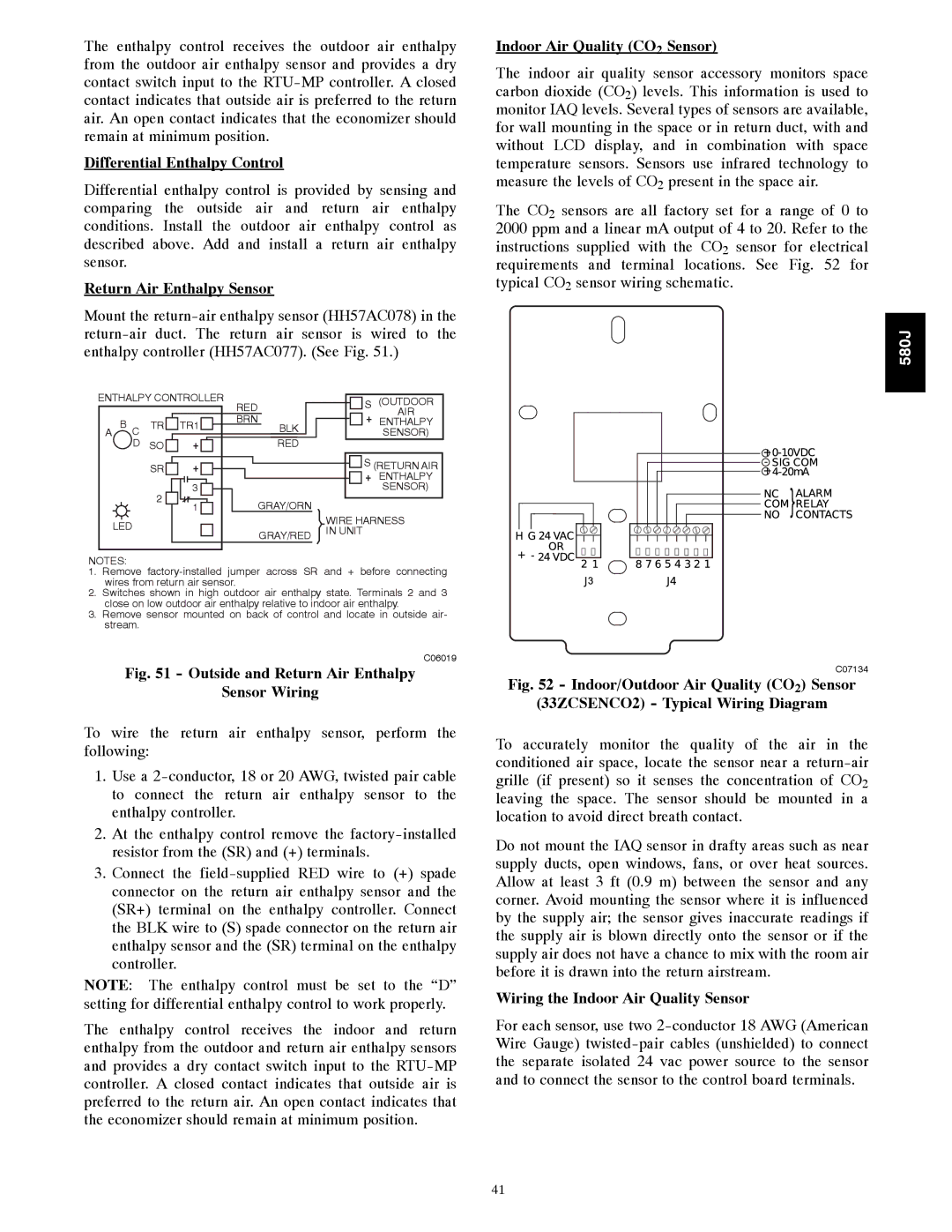
Return Air Enthalpy Sensor
Indoor Air Quality CO2 Sensor
Outdoor Air Quality Sensor PNO 33ZCSENCO2 plus
Connecting Discrete Inputs
Weatherproof Enclosure
Filter Status
Communication Wiring Protocols
Power Exhaust output
Communication LEDs
RTU-MP Troubleshooting
Protocol DS8 DS7 DS6 DS5 DS4 DS3 DS2 DS1
Baud Rate DS2 DS1
LEDs on the RTU-MP show the status of certain functions
LEDs
Troubleshooting Alarms
BACnet MS/TP
Alarms
Module Status Report Modstat Example
Modbus
Basic Protocol Troubleshooting
Manufacture Date
Code Name Meaning
EconoMi$er IV Component Locations
ECONOMI$ER Systems
EconoMi$er IV Wiring
EconoMi$er IV Functional View
EconoMi$er IV Input/Output Logic
Outdoor Air Lockout Sensor
Supply Air Temperature SAT Sensor
EconoMi$er IV Control Modes
Outdoor Dry Bulb Changeover
Outdoor Enthalpy Changeover
Differential Dry Bulb Control
Minimum Position Control
Exhaust Setpoint Adjustment
Indoor Air Quality IAQ Sensor Input
Demand Control Ventilation DCV
Damper Movement
Thermostats
Analog CO2
CO2 Sensor Configuration
CO2 Sensor Standard Settings
EconoMi$er IV Sensor Usage
DCV Demand Controlled Ventilation and Power Exhaust
EconoMi$er IV Preparation
Differential Enthalpy
EconoMi$er IV Troubleshooting Completion
Wiring Diagrams
DCV Minimum and Maximum Position
Supply-Air Sensor Input
580J Typical Unit Wiring Diagram Power 08D,F, 208/230-3-60
C09157
START-UP, General
PRE-START-UP
Unit Preparation
Gas Piping
Refrigerant Service Ports
Internal Wiring
Return-Air Filters
Outdoor-Air Inlet Screens
Configuration
Field Service Test
Unit Start Delay
START-UP, RTU-MP Control
Supply Fan Service Hours
Filter Service Hours
Compressor1 Service Hours
Compressor2 Service Hours
Space Sensor Type
Input
Input 1 Function
Input 2 Function
Base Unit Controls Cooling, Units Without Economizer
Operating Sequences
Heating, Units Without Economizer
Cooling, Unit With EconoMi$er
Demand Controlled Ventilation
Heating With EconoMi$er
Supplemental Controls
RTU-MP Sequence of Operation
Scheduling
Always Occupied Default Occupancy
Local Schedule
BACnet Schedule
Economizer
Power Exhaust
Cooling
Indoor Air Quality
Fastener Torque Values
Demand Limit
Torque Values
Model Number Nomenclature
Appendix I. Model Number Significance
Serial Number Format
Position Number
12.5TONS
Appendix II. Physical Data
Physical Data
Physical Data Heating 12.5TONS
Heat Anticipator Setting Amps
580J**08 580J**12 580J**14 Gas Connection
Natural Gas Heat, Liquid Propane Heat
CFM RPM BHP
Appendix III. FAN Performance
580J**08
579
580J**12
RPM BHP
580J**14
1260
General fan performance notes
Unit MOTOR/DRIVE Motor Pulley Turns Open Combo
Pulley Adjustment
Electrical Information
NOM IFM FAN Motor Exhaust No P.E
Unit Combustion Power
Type DISC. Size
Mocp
Wiring Diagrams
Appendix IV. Wiring Diagram List
Catalog No.SM580J---02
Appendix V. Motormaster Sensor Locations
580J
Preliminary Information
Unit START-UP Checklist