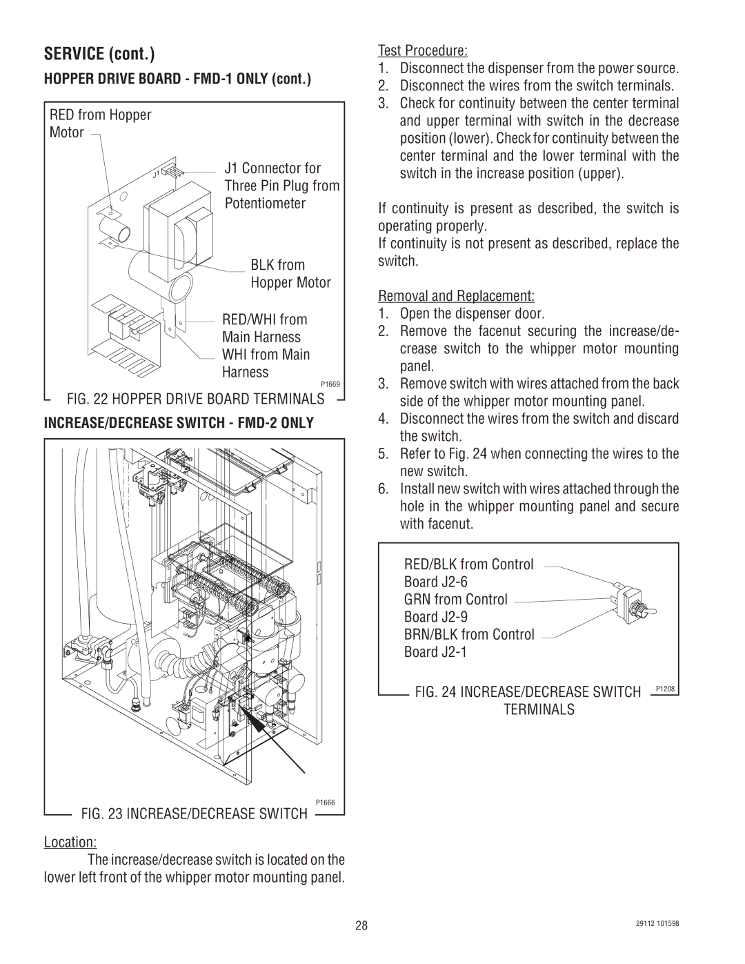
FMD-1 FMD-2 specifications
The Bunn FMD-1 and FMD-2 models represent a significant advancement in the realm of coffee brewing equipment, catering to the demands of both commercial establishments and serious coffee enthusiasts. These machines are designed to efficiently brew high-quality coffee while minimizing operational complexity.The Bunn FMD-1 is a single brewer, while the FMD-2 features dual brewing capabilities. This distinction allows the FMD-2 to meet higher coffee volume demands, making it an ideal choice for bustling cafes or restaurants where efficiency is paramount. Both models are engineered with a robust stainless steel construction, ensuring durability and longevity in high-traffic environments.
One standout feature of both models is the infusion technology. This proprietary system enhances the extraction process, allowing for optimal flavor development. The machines utilize a programmable brewing timeline, which provides users with a high level of control over the brewing variables such as time and temperature. This leads to a customizable brewing experience tailored to specific coffee blends or personal taste preferences.
Additionally, these brewers are equipped with an integrated hot water faucet, offering convenience for making tea, hot chocolate, or even instant soup. This multifunctionality improves workflow in busy kitchens, as it eliminates the need for separate hot water dispensers.
The FMD series is also designed with user-friendly interfaces. The digital display provides clear, intuitive information about the brewing process, including brew progress and maintenance alerts. This makes it easy for operators to monitor and manage the machine, ensuring consistency and quality in every cup.
Moreover, both models are designed for quick and efficient cleaning. The removable brewing components facilitate maintenance, which is crucial in a commercial setting where hygiene and equipment uptime are critical.
In terms of capacity, the FMD-1 brews up to 3.8 gallons per hour, while the FMD-2 can produce an impressive 7.5 gallons per hour, demonstrating their suitability for high-volume service.
Overall, the Bunn FMD-1 and FMD-2 models embody the perfect blend of technology, efficiency, and user-centric design, making them a valuable addition to any coffee service operation. Their ability to deliver consistent, high-quality coffee with ease is sure to enhance the customer experience and streamline operations simultaneously.

