SERVICE (cont.)
OVERFLOW PROTECTION SWITCH
P1199.45 |
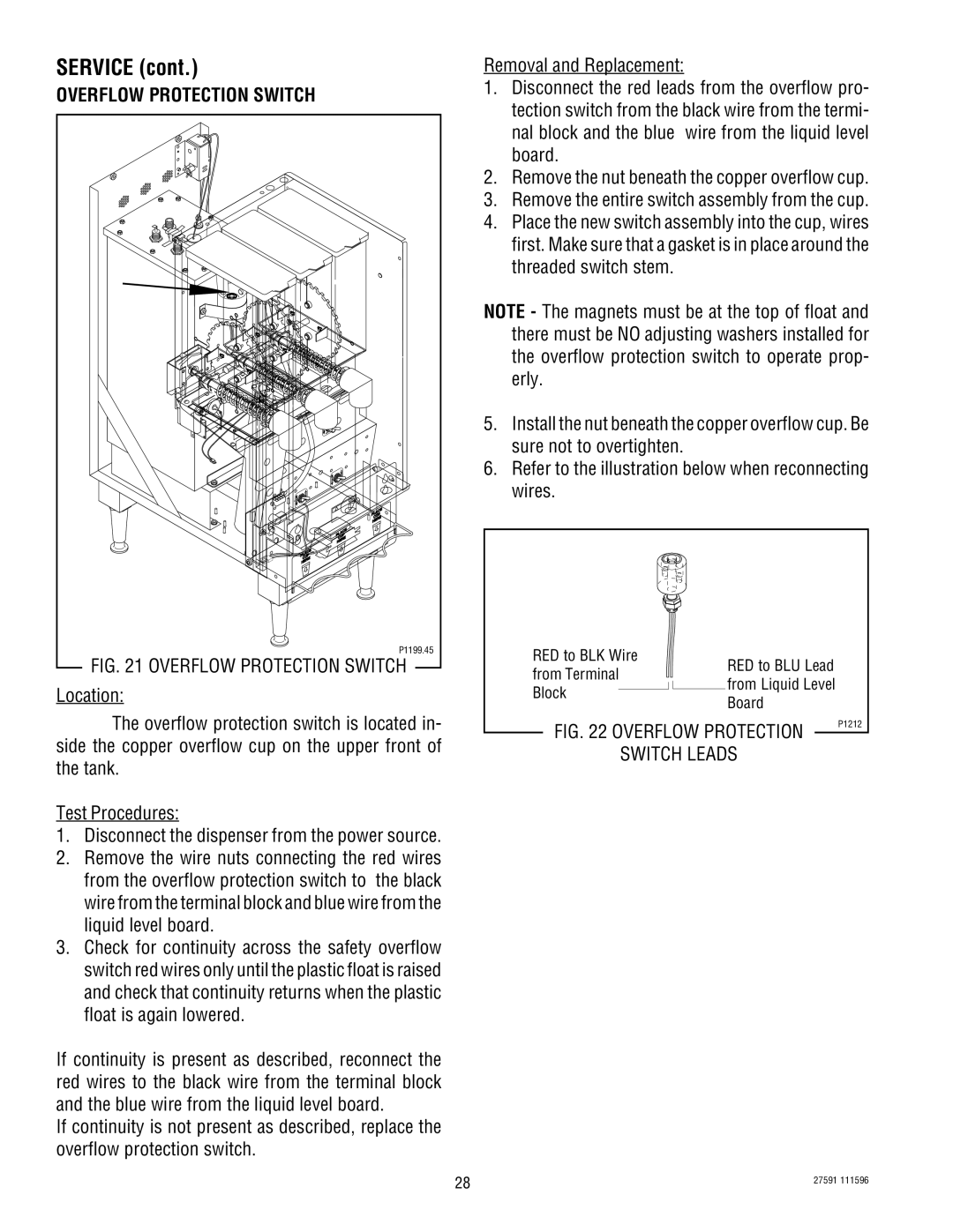
FIG. 21 OVERFLOW PROTECTION SWITCH |
Location: |
Removal and Replacement:
1.Disconnect the red leads from the overflow pro- tection switch from the black wire from the termi- nal block and the blue wire from the liquid level board.
2.Remove the nut beneath the copper overflow cup.
3.Remove the entire switch assembly from the cup.
4.Place the new switch assembly into the cup, wires first. Make sure that a gasket is in place around the threaded switch stem.
NOTE - The magnets must be at the top of float and there must be NO adjusting washers installed for the overflow protection switch to operate prop- erly.
5.Install the nut beneath the copper overflow cup. Be sure not to overtighten.
6.Refer to the illustration below when reconnecting wires.
RED to BLK Wire |
|
| RED to BLU Lead | |
from Terminal |
|
| ||
|
| from Liquid Level | ||
|
|
|
| |
Block |
|
| Board | |
|
|
|
| |
The overflow protection switch is located in- side the copper overflow cup on the upper front of the tank.
Test Procedures:
1.Disconnect the dispenser from the power source.
2.Remove the wire nuts connecting the red wires from the overflow protection switch to the black wire from the terminal block and blue wire from the liquid level board.
3.Check for continuity across the safety overflow switch red wires only until the plastic float is raised and check that continuity returns when the plastic float is again lowered.
If continuity is present as described, reconnect the red wires to the black wire from the terminal block and the blue wire from the liquid level board.
If continuity is not present as described, replace the overflow protection switch.
FIG. 22 OVERFLOW PROTECTION
SWITCH LEADS
P1212
28 | 27591 111596 |
|