SEHI100TX-22 specifications
Cabletron Systems SEHI100TX-22 is a high-performance network interface card that has been designed for reliable data transfer in various networking environments. Ideal for both enterprise and small business applications, the SEHI100TX-22 delivers exceptional performance at a competitive price point.One of the standout features of the SEHI100TX-22 is its support for 100Base-TX Ethernet standards, which enables high-speed data transmission at rates of up to 100 Mbps. This high throughput capacity makes it an excellent choice for organizations that require swift and efficient data handling, particularly in environments with heavy network traffic.
The card is equipped with two RJ-45 connectors, allowing it to support dual-port configurations. This dual-port setup enhances networking capabilities by enabling fault tolerance and load balancing, ensuring that the network remains operational even in the event of a failure. Moreover, it supports full-duplex operation, allowing for simultaneous bi-directional data transmission, further improving overall network efficiency and performance.
Another significant advantage of the SEHI100TX-22 is its compatibility with a wide range of operating systems and platforms, including Windows, Linux, and various UNIX variants. This versatility ensures that it can be seamlessly integrated into existing network infrastructures without the need for extensive configuration or modification.
In terms of installation and maintenance, the SEHI100TX-22 is user-friendly, thanks to its Plug and Play capability. This feature allows for easy installation; users can simply insert the card into an available PCI slot, and the operating system will automatically recognize and configure the device, minimizing downtime and simplifying the setup process.
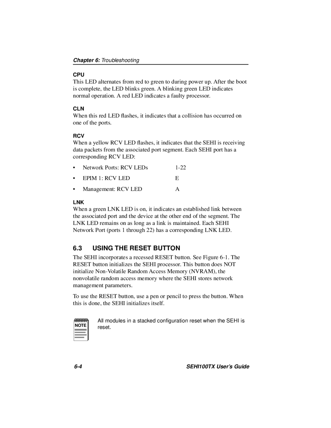
Additionally, the SEHI100TX-22 incorporates advanced technologies like Auto-Negotiation, which automatically detects the speed and duplex capabilities of the connected device, thus optimizing the network performance. The card also features various onboard diagnostic LEDs, providing real-time feedback on connection status and data activity, which aids in troubleshooting and performance monitoring.
In summary, the Cabletron Systems SEHI100TX-22 offers a robust set of features that cater to the demands of modern network environments. With its high-speed capabilities, dual-port support, compatibility across multiple operating systems, and user-friendly installation process, it remains a solid choice for organizations looking to enhance their networking performance and reliability.

