The WAN Interface Configuration Screen
3.2THE WAN INTERFACE CONFIGURATION SCREEN
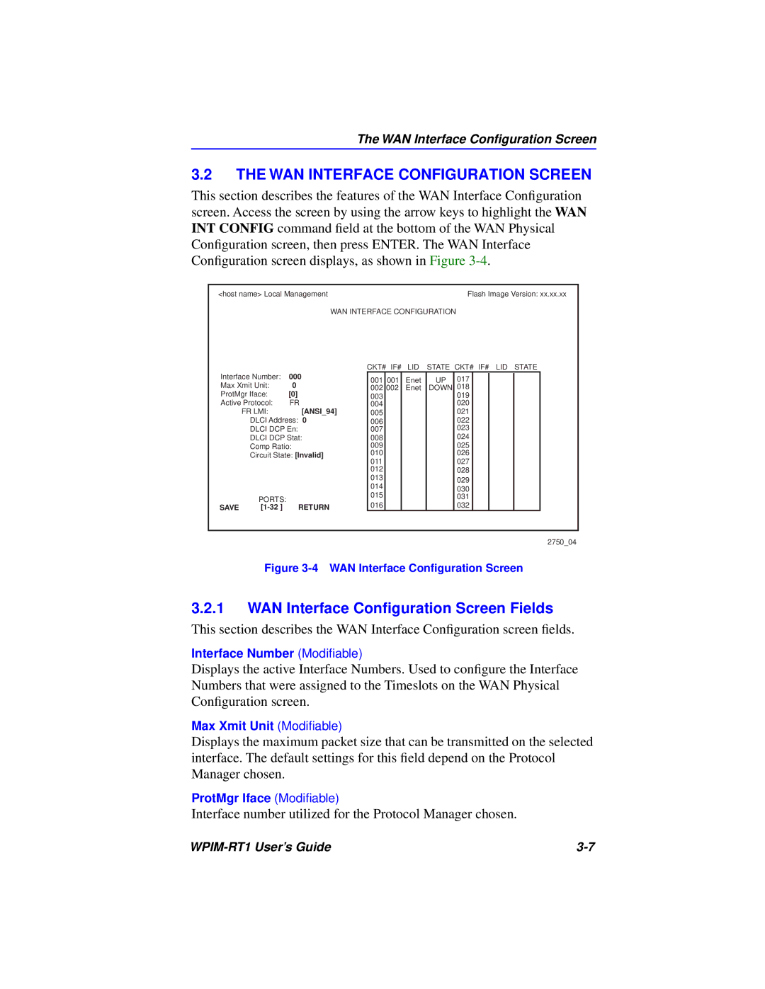
This section describes the features of the WAN Interface Configuration screen. Access the screen by using the arrow keys to highlight the WAN INT CONFIG command field at the bottom of the WAN Physical Configuration screen, then press ENTER. The WAN Interface Configuration screen displays, as shown in Figure
<host name> Local Management |
|
|
|
| Flash Image Version: xx.xx.xx | ||||||
|
| WAN INTERFACE CONFIGURATION | |||||||||
|
|
| CKT# IF# | LID | STATE CKT# IF# LID STATE | ||||||
Interface Number: | 000 | 001 | 001 | Enet | UP | 017 |
|
|
|
| |
Max Xmit Unit: | 0 |
|
|
|
| ||||||
002 | 002 | Enet | DOWN | 018 |
|
|
|
| |||
ProtMgr Iface: | [0] | 003 |
|
|
| 019 |
|
|
|
| |
Active Protocol: | FR | 004 |
|
|
| 020 |
|
|
|
| |
| FR LMI: | [ANSI_94] | 005 |
|
|
| 021 |
|
|
|
|
| DLCI Address: 0 | 006 |
|
|
| 022 |
|
|
|
| |
| DLCI DCP En: | 007 |
|
|
| 023 |
|
|
|
| |
| DLCI DCP Stat: | 008 |
|
|
| 024 |
|
|
|
| |
| Comp Ratio: | 009 |
|
|
| 025 |
|
|
|
| |
| Circuit State: [Invalid] | 010 |
|
|
| 026 |
|
|
|
| |
| 011 |
|
|
| 027 |
|
|
|
| ||
|
|
|
|
|
|
|
|
|
| ||
|
|
| 012 |
|
|
| 028 |
|
|
|
|
|
|
| 013 |
|
|
| 029 |
|
|
|
|
|
|
| 014 |
|
|
|
|
|
|
| |
|
|
|
|
|
| 030 |
|
|
|
| |
| PORTS: |
| 015 |
|
|
| 031 |
|
|
|
|
|
| 016 |
|
|
| 032 |
|
|
|
| |
SAVE | RETURN |
|
|
|
|
|
|
| |||
2750_04
Figure 3-4 WAN Interface Configuration Screen
3.2.1WAN Interface Configuration Screen Fields
This section describes the WAN Interface Configuration screen fields.
Interface Number (Modifiable)
Displays the active Interface Numbers. Used to configure the Interface Numbers that were assigned to the Timeslots on the WAN Physical Configuration screen.
Max Xmit Unit (Modifiable)
Displays the maximum packet size that can be transmitted on the selected interface. The default settings for this field depend on the Protocol Manager chosen.
ProtMgr Iface (Modifiable)
Interface number utilized for the Protocol Manager chosen.
|
