Chapter 3: Local Management
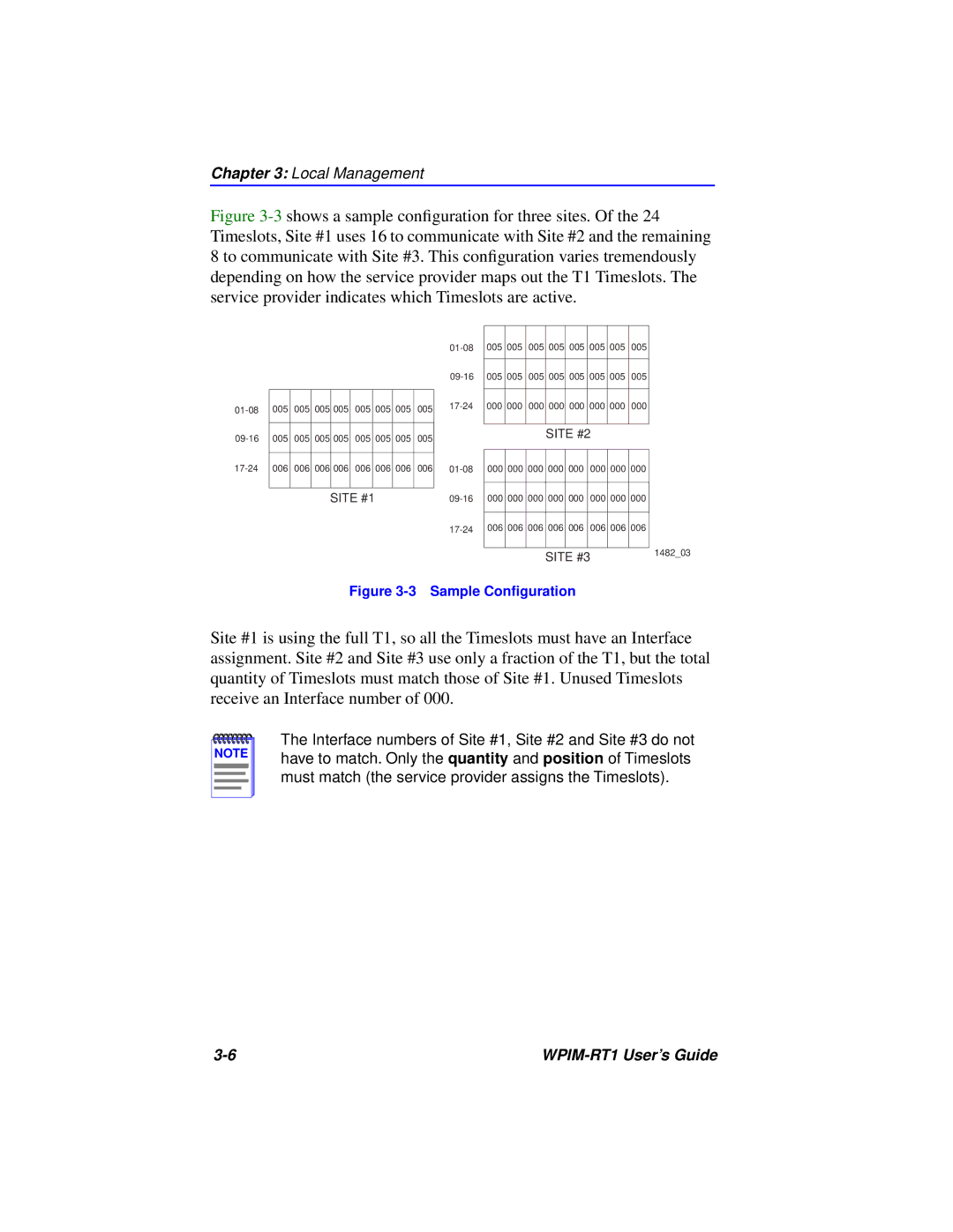
Figure 3-3 shows a sample configuration for three sites. Of the 24 Timeslots, Site #1 uses 16 to communicate with Site #2 and the remaining 8 to communicate with Site #3. This configuration varies tremendously depending on how the service provider maps out the T1 Timeslots. The service provider indicates which Timeslots are active.
|
|
|
|
|
|
|
|
| 005 | 005 | 005 | 005 | 005 | 005 | 005 | 005 | |
|
|
|
|
|
|
|
|
|
|
|
|
|
|
|
|
| |
|
|
|
|
|
|
|
|
| 005 | 005 | 005 | 005 | 005 | 005 | 005 | 005 | |
|
|
|
|
|
|
|
|
|
|
|
|
|
|
|
|
| |
005 | 005 | 005 | 005 | 005 | 005 | 005 | 005 | 000 | 000 | 000 | 000 | 000 | 000 | 000 | 000 | ||
|
|
|
|
|
|
|
|
| |||||||||
|
|
|
|
|
|
|
|
|
|
|
|
|
|
|
|
|
|
005 | 005 | 005 | 005 | 005 | 005 | 005 | 005 |
|
|
|
| SITE #2 |
|
| |||
|
|
|
|
|
|
|
|
| |||||||||
|
|
|
|
|
|
|
|
|
|
|
|
|
|
|
|
| |
006 | 006 | 006 | 006 | 006 | 006 | 006 | 006 | 000 | 000 | 000 | 000 | 000 | 000 | 000 | 000 | ||
|
|
|
|
|
|
|
|
|
|
|
|
|
|
|
|
|
|
|
|
|
|
|
|
|
|
|
|
|
|
|
|
|
|
|
|
|
|
| SITE #1 |
|
|
| 000 | 000 | 000 | 000 | 000 | 000 | 000 | 000 | |||
|
|
|
|
|
|
|
|
|
|
|
|
|
|
|
|
|
|
|
|
|
|
|
|
|
|
| 006 | 006 | 006 | 006 | 006 | 006 | 006 | 006 | |
|
|
|
|
|
|
|
|
|
|
|
|
|
|
|
|
|
|
SITE #3 | 1482_03 |
|
Figure 3-3 Sample Configuration
Site #1 is using the full T1, so all the Timeslots must have an Interface assignment. Site #2 and Site #3 use only a fraction of the T1, but the total quantity of Timeslots must match those of Site #1. Unused Timeslots receive an Interface number of 000.
NOTE |
The Interface numbers of Site #1, Site #2 and Site #3 do not have to match. Only the quantity and position of Timeslots must match (the service provider assigns the Timeslots).
|