Cordless Air Compressor
Modelo FP2400 |
Pre-Operation (Cont.)
INDICATOR LIGHTS
The indicator lights on the unit read as follows:
Green. Fully charged and ready to run.
Yellow. Partially discharged and operational.
Red. Battery is low. Unit will not operate to protect battery.
Yellow and Red Flashing. Unit is on
charge and will not operate.
your area, call
The environmental laws in some states require retailers to accept returns of rechargeable batteries for proper disposal. Check the state environmental laws before disposing of this product. Never throw the battery pack away in a standard receptacle or have it incinerated. Contact your local city officials for battery disposal information.
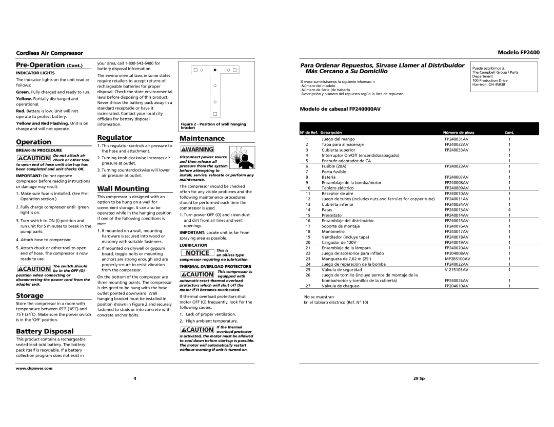
Figure 2 - Position of wall hanging bracket
Para Ordenar Repuestos, Sírvase Llamer al Distribuidor | Puede escribirnos a: | ||
Más Cercano a Su Domicilio |
| ||
| The Campbell Group / Parts | ||
|
| Department |
|
Sírvase suministrarnos la siguiente información |
| 100 Production Drive | |
| Harrison, OH 45030 | ||
| |||
|
|
| |
|
|
| |
|
|
| |
Modelo de cabezal FP240000AV |
|
|
|
Nº de Ref. Descripción | Número de pieza | Cant. | |
Operation
BREAK-IN PROCEDURE
Do not attach air
! CAUTION chuck or other tool to open end of hose until
IMPORTANT: Do not operate compressor before reading instructions or damage may result.
1.Make sure fuse is installed. (See Pre- Operation section.)
2.Fully charge compressor until green light is on.
3.Turn switch to ON (I) position and run unit for 5 minutes to break in the pump parts.
4.Attach hose to compressor.
5.Attach chuck or other tool to open end of hose. The compressor is now ready to use.
The switch should
! CAUTION be in the OFF (O) position when connecting or disconnecting the power cord from the adapter jack.
Storage
Store the compressor in a room with temperature between 65oF (18oC) and 75oF (24oC). Make sure the power switch is in the 'Off' position.
Battery Disposal
This product contains a rechargeable sealed
Regulator
1.This regulator controls air pressure to the hose and attachment.
2.Turning knob clockwise increases air pressure at outlet.
3.Turning counterclockwise will lower air pressure at outlet.
Wall Mounting
This compressor is designed with an option to be hung on a wall for convenient storage. It can also be operated while in the hanging position if one of the following conditions is met:
1.If mounted on a wall, mounting hardware is secured into wood or masonry with suitable fasteners.
2.If mounted on drywall or gypsum board, toggle bolts or mounting anchors are strong enough and are properly secure to resist vibration from the compressor.
On the bottom of the compressor are three mounting points. The compressor is designed to be hung with the hose outlet pointed downward. Wall hanging bracket must be installed in position shown in Figure 2 and securely fastened to studs or into concrete with concrete anchor bolts.
Maintenance
! WARNING
Disconnect power source and then release all pressure from the system before attempting to
install, service, relocate or perform any maintenance.
The compressor should be checked often for any visible problems and the following maintenance procedures should be performed each time the compressor is used.
1.Turn power OFF (O) and clean dust and dirt from air lines and vent openings.
IMPORTANT: Locate unit as far from spraying area as possible.
LUBRICATION
This is
NOTICE an oilless type compressor requiring no lubrication.
THERMAL OVERLOAD PROTECTORS
This compressor is
! CAUTION equipped with automatic reset thermal overload protectors which will shut off the motor if it becomes overheated.
If thermal overload protectors shut motor OFF (O) frequently, look for the following causes.
1.Lack of proper ventilation.
2.High ambient temperature.
If the thermal
!CAUTION overload protector is activated, the motor must be allowed to cool down before
1 | Juego del mango | FP240031AV | 1 |
2 | Tapa para almacenaje | FP240032AV | 1 |
3 | Cubierta superior | FP240033AV | 1 |
4 | Interruptor On/Off (encendido/apagado) | ■ | 1 |
5 | Enchufe adaptador de CA | ■ | 1 |
6 | Fusible (20A) | FP240023AV | 1 |
7 | Porta fusible | ■ | 1 |
8 | Batería | FP240007AV | 1 |
9 | Ensamblaje de la bomba/motor | FP240008AV | 1 |
10 | Tablero eléctrico | FP240009AV | 1 |
11 | Receptor de aire | FP240010AV | 1 |
12 | Juego de tubos (includes nuts and ferrules for copper tube) | FP240011AV | 1 |
13 | Cubierta inferior | FP240034AV | 1 |
14 | Patas | FP240013AV | 4 |
15 | Presóstato | FP240014AV | 1 |
16 | Ensamblaje del distribuidor | FP240015AV | 1 |
17 | Soporte de montaje | FP240016AV | 1 |
18 | Manómetro | FP240017AV | 1 |
19 | Ventilador (incluye tapa) | FP240018AV | 1 |
20 | Cargador de 120V ▲ | FP240019AV | 1 |
21 | Ensamblaje de la lámpara | FP240020AV | 1 |
22 | Juego de accesorios para inflado ▲ | FP204008AV | 1 |
23 | Manguera de 7,62 m (25’) ▲ | MP285100AV | 1 |
24 | Juego de reparación de la bomba ▲ | FP240022AV | 1 |
25 | Válvula de seguridad | 1 | |
26 | Juego de tornillo (incluye pernos de montaje de la |
|
|
| bomba/motor y tornillos de la cubierta) ▲ | FP240024AV | 1 |
27 | Valvula de chequeo ▲ | FP204010AV | 1 |
▲No se muestran
■En el tablero eléctrico (Ref. Nº 10)
www.chpower.com
4 | 29 Sp |