Operating Instructions and Parts Manual
Maintenance (continued)
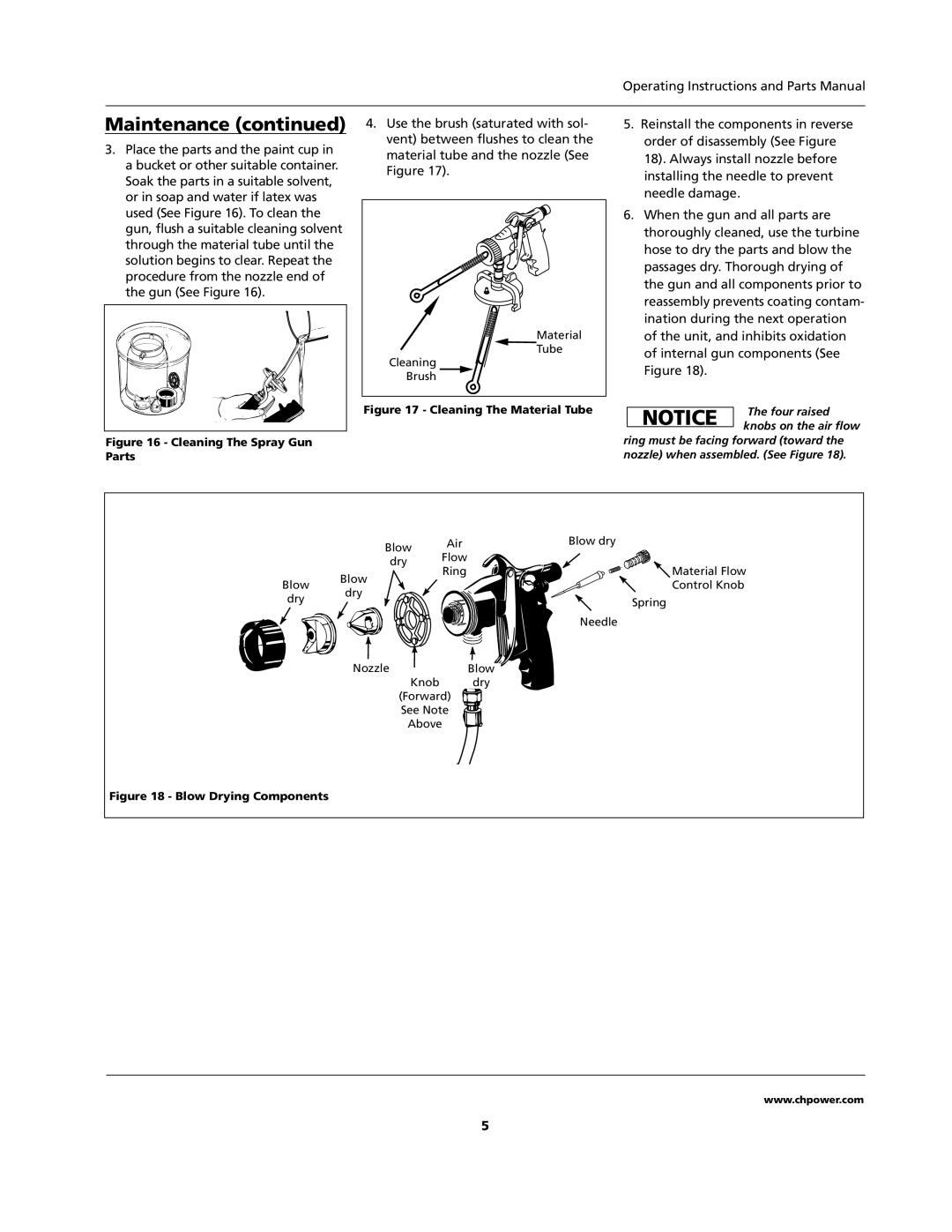
3.Place the parts and the paint cup in a bucket or other suitable container. Soak the parts in a suitable solvent, or in soap and water if latex was used (See Figure 16). To clean the gun, flush a suitable cleaning solvent through the material tube until the solution begins to clear. Repeat the procedure from the nozzle end of the gun (See Figure 16).
Figure 16 - Cleaning The Spray Gun Parts
4.Use the brush (saturated with sol- vent) between flushes to clean the material tube and the nozzle (See Figure 17).
Material |
Tube |
Cleaning |
Brush |
Figure 17 - Cleaning The Material Tube
5.Reinstall the components in reverse order of disassembly (See Figure
18). Always install nozzle before installing the needle to prevent needle damage.
6.When the gun and all parts are thoroughly cleaned, use the turbine hose to dry the parts and blow the passages dry. Thorough drying of the gun and all components prior to reassembly prevents coating contam- ination during the next operation of the unit, and inhibits oxidation of internal gun components (See Figure 18).
NOTICE | The four raised | |
knobs on the air flow | ||
|
ring must be facing forward (toward the nozzle) when assembled. (See Figure 18).
| Blow | Air | Blow dry | |
| Flow |
| ||
| dry |
|
| |
|
| Ring | Material Flow | |
| Blow |
| ||
Blow |
|
| Control Knob | |
dry |
|
| ||
dry |
|
| Spring | |
|
|
| ||
|
|
|
| |
|
|
|
| Needle |
| Nozzle |
|
| Blow |
|
| Knob |
| dry |
| (Forward) |
| ||
| See Note |
| ||
|
| Above |
| |
Figure 18 - Blow Drying Components
www.chpower.com
5
