Table 15 — Weight Distribution, Compressor
Units (See drawing, Table 14)
COMPR | WT DISTR (lb) | NEMA FRAME SIZE | ||
A or D | B or C | |||
|
| |||
|
|
| Belt Drive | |
5F20 | 115 | 100 | 182T, 184T, 213T, 215T | |
5F30 | 140 | 118 | 184T, 213T, 215T, 254T | |
5F30* | 168 | 145 | 184T, 213T, 215T, 254T | |
5F40 | 228 | 165 | 213T, 215T, 254T, 256T | |
5F60 | 280 | 210 | 215T, 254T, 256T, 284T | |
5H40 | 410 | 305 | 256T, 284T, 286T, 324T, 326T | |
5H60 | 515 | 395 | 286T, 324T, 326T | |
5H60* | 630 | 533 | 324T, 326T, 364T, 365T | |
5H80 | 685 | 558 | 324T, 326T, 364T, 365T, 404T | |
5H120 | 1050 | 728 | 364T, 365T, 404T | |
|
|
| Direct Drive | |
5F40 | 210 | 145 | 213T, 215T, 254T, 256T | |
5F60 | 245 | 185 | 215T, 254T, 256T, 284T, 286T | |
5F60* | 290 | 255 | 256T, 284T, 286T | |
5H40 | 380 | 275 | 256T, 284T, 286T, 324TS, 326TS | |
5H46 | 380 | 275 | 324TS, 326TS, 364TS, 365TS | |
5H80 | 480 | 360 | 286T, 324TS, 326TS, 364TS | |
5H60 | 480 | 360 | 365TS, 404TS | |
5H66 | 480 | 360 | 286T, 324TS, 326TS, 364TS, 365TS, | |
404TS | ||||
5H80 |
|
| ||
690 | 605 | 324TS, 326TS, 364TS, 365TS, 404TS | ||
5H86 | 690 | 605 | 365TS, 404TS, 405TS | |
5H120 | 890 | 690 | 364TS, 365TS, 404TS, 405TS, 444TS | |
5H126 | 890 | 690 | 405TS, 444TS, 445TS | |
LEGEND
NEMA — National Electrical Manufacturers Association *Oversize frame.
Capacity Control — For all 5F,H compressors, a
The cylinder unloading mechanism is powered by a compressor
1 |
|
|
|
| 2 |
|
| 1 |
5F20 |
| 5F30 |
1 | 2 | 1 |
|
|
3 2
4 3
5F40 | 5F60 |
A
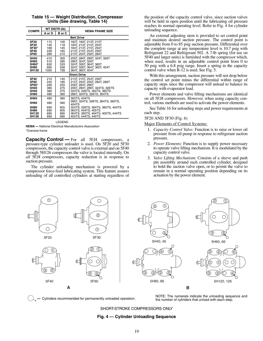
![]() — Cylinders recommended for permanently unloaded operation.
— Cylinders recommended for permanently unloaded operation.
the position of the capacity control valve, since suction valves will be held in open position until the lubricating oil pressure reaches its normal operating level. Refer to Fig. 4 for cylinder unloading sequence.
An external adjusting stem is provided to set control point and maintain desired suction pressure. The control point is adjustable from 0 to 85 psig suction pressure. Differential over the complete range at any temperature level is 10.7 psig with Refrigerant 22 and Refrigerant 502. A
With this arrangement, suction pressure will not drop below the control set point minus the differential within range of capacity steps since the compressor will unload to balance its capacity with evaporator load.
Power elements and valve lifting mechanisms are identical on all 5F,H compressors. However, when using capacity con- trol, various methods are used to activate the power elements.
See Table 16 for unloading steps and power requirements at each step.
5F20 AND 5F30 (Fig. 6)
Major Elements of Control Systems:
1.Capacity Control Valve: Function is to raise or lower oil pressure from oil pump in response to refrigerant suction pressure.
2.Power Elements: Function is to supply power necessary to operate valve lifting mechanism. It is modulated by the capacity control valve.
3.Valve Lifting Mechanism: Consists of a sleeve and push pin assembly around each controlled cylinder, designed to hold the suction valve open, or to permit the valve to remain in a normal operating position depending on its actuation by the power element.
2 1
2 1
|
| 3 |
|
| 4 | 3 |
| 5H40, 46 |
|
| 5H60, 66 | ||
|
| 4 | 1 | 2 | 2 | 4 |
|
|
|
| 1 | 1 |
|
3 | 3 | 2 | 2 | 3 | 3 | 4 |
| 5H80, 86 |
|
| 5H120, 126 | ||
B
NOTE: The numerals indicate the unloading sequence and the number of cylinders that unload with each step.
Fig. 4 — Cylinder Unloading Sequence
19