Table 16 — Capacity Control Reduction Steps
|
|
|
| CAP. STEPS (% Full Load Cap.) |
|
|
| ||||||||
|
| 100 | 871/ | 831/ | 3 | 75 | 662/ | 3 | 621/ | 2 | 50 | 371/ | 331/ | 3 | 25 |
COMPR | CONTR |
| 2 |
|
|
|
|
| 2 |
|
| ||||
|
|
|
| % Full Load Bhp |
|
|
|
| |||||||
MODEL | CYL |
|
|
|
|
|
|
|
| ||||||
|
| 100 | 90 | 86 |
| 80 | 74 |
| 71 |
| 60 | 50 | 45 |
| 38 |
|
|
|
| Number of Active Cylinders |
|
|
| ||||||||
5F20 | 1 | 2 | — | — |
| — | — |
| — |
| 1 | — | — |
| — |
5F30* | 1 | 3 | — | — |
| — | 2 |
| — |
| — | — | — |
| — |
5F40 | 3 | 4 | — | — |
| 3 | — |
| — | 2 | — | — | 1 | ||
5F60 | 4 | 6 | — | 5 |
| — | 4 |
| — |
| 3 | — | 2 |
| — |
5H40 | 3 | 4 | — | — | 3 | — | — | 2 | — | — | 1 | ||||
5H46 | 3 | 4 | — | — |
| 3 | — |
| — | 2 | — | — | 1 | ||
5H60 | 4 | 6 | — | 5 |
| — | 4 |
| — |
| 3 | — | 2 |
| — |
5H66 | 4 | 6 | — | 5 |
| — | 4 |
| — |
| 3 | — | 2 |
| — |
5H80 | 6 | 8 | 7 | — |
| — | — |
| 5 |
| — | 3 | — |
| 2 |
5H86 | 6 | 8 | 7 | — |
| — | — |
| 5 |
| — | 3 | — |
| 2 |
5H120 | 8 | 12 | — | 10 |
| — | 8 |
| — |
| 6 | — | 4 |
| — |
5H126 | 8 | 12 | — | 10 |
| — | 8 |
| — |
| 6 | — | 4 |
| — |
*Two controlled cylinders (to 331/3%) available on request for 5F30.
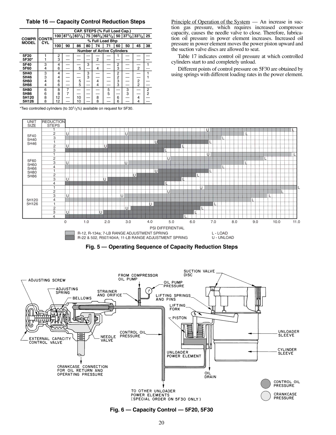
Principle of Operation of the System — An increase in suc- tion gas pressure, which requires increased compressor capacity, causes the needle valve to close. Therefore, lubrica- tion oil pressure in power element increases. Increased oil pressure in power element moves the power piston upward and the suction valve discs are allowed to seat.
Table 17 indicates control oil pressure at which controlled cylinders start to and completely unload.
Different points of control pressure on 5F30 are obtained by using springs with different loading rates in the power element.
UNIT | REDUCTION |
|
|
|
|
|
|
|
|
|
|
|
|
|
|
|
|
|
|
|
|
|
|
|
|
|
|
|
|
|
|
|
|
|
|
| ||
SIZE | STEPS |
|
|
|
|
|
|
|
|
|
|
|
|
|
|
|
|
|
|
|
|
|
|
|
|
|
|
|
|
|
|
|
|
|
| L | ||
| 1 |
|
|
|
|
|
|
|
|
|
|
|
|
|
|
|
|
|
|
|
|
|
|
| U |
|
|
|
|
|
|
|
|
|
| |||
5F40 | 2 |
| U |
|
|
|
|
|
| U |
|
|
|
|
|
|
|
|
|
|
|
|
|
|
|
|
|
|
| L |
|
|
|
|
|
| ||
5H40 | 3 |
|
|
|
|
|
|
|
|
|
|
|
|
|
|
|
|
|
|
|
|
|
|
|
|
|
|
| L |
|
|
|
|
|
|
|
|
|
5H46 | 1 |
|
|
|
|
|
|
|
|
|
|
|
|
| U |
|
|
|
|
|
|
| L |
|
|
|
|
|
|
|
|
| ||||||
| 2 |
| U |
|
| U |
|
|
|
|
|
|
|
|
|
|
|
| L |
|
|
|
|
|
|
|
|
|
|
|
|
| ||||||
| 3 |
|
|
|
|
|
|
|
|
|
|
|
|
|
|
|
| L |
|
|
|
|
|
|
|
|
|
|
|
|
|
|
|
|
|
|
| |
| 1 |
|
|
|
|
|
|
|
|
|
|
|
|
|
|
|
|
|
|
|
|
|
|
| U |
|
|
|
|
|
|
|
|
|
| L |
|
|
5F60 | 2 |
|
|
|
|
|
|
|
|
|
|
|
|
|
|
|
| U |
|
|
|
|
|
|
|
|
|
|
|
|
|
| L |
|
|
|
| |
5H60 | 3 |
| U |
|
|
|
|
|
| U |
|
|
|
|
|
|
|
|
|
|
|
|
|
|
|
|
|
|
| L |
|
|
|
|
|
| ||
5H66 | 4 |
|
|
|
|
|
|
|
|
|
|
|
|
|
|
|
|
|
|
|
|
|
|
|
|
|
|
| L |
|
|
|
|
|
|
|
|
|
5H80 | 1 |
|
|
|
|
|
|
|
|
|
|
|
|
| U |
|
|
|
|
|
|
|
|
| L |
|
|
|
|
|
|
|
|
| ||||
5H86 | 2 |
|
|
|
|
|
|
|
|
|
|
| U |
|
|
|
|
|
|
|
|
| L |
|
|
|
|
|
|
|
|
|
|
|
|
| ||
| 3 |
| U |
|
| U |
|
|
|
|
|
|
|
|
|
|
|
| L |
|
|
|
|
|
|
|
|
|
|
|
|
| ||||||
| 4 |
|
|
|
|
|
|
|
|
|
|
|
|
|
|
|
| L |
|
|
|
|
|
|
|
|
|
|
|
|
|
|
|
|
|
| L | |
| 1 |
|
|
|
|
|
|
|
|
|
|
|
|
|
|
|
|
|
|
|
|
| U |
|
|
|
|
|
|
|
|
|
|
|
|
| ||
| 2 |
|
|
|
|
|
|
|
|
|
|
|
|
|
|
|
| U |
|
|
|
|
|
|
|
|
|
|
|
|
|
|
|
| L | |||
5H120 | 3 |
| U |
|
|
|
|
| U |
|
|
|
|
|
|
|
|
|
|
|
|
|
|
|
|
|
|
|
|
|
|
|
| L |
|
|
|
|
4 |
|
|
|
|
|
|
|
|
|
|
|
|
|
|
|
|
|
|
|
|
|
|
|
|
|
|
|
|
|
| L |
|
|
|
|
|
| |
5H126 | 1 |
|
|
|
|
|
|
|
|
|
|
|
| U |
|
|
|
|
|
|
|
|
|
|
|
|
| L |
|
|
|
|
|
|
|
|
| |
| 2 |
|
|
|
|
|
|
|
| U |
|
|
|
|
|
|
|
|
|
|
| L |
|
|
|
|
|
|
|
|
|
|
|
|
| |||
| 3 |
| U |
| U |
|
|
|
|
|
|
|
|
|
|
|
|
|
|
|
| L |
|
|
|
|
|
|
|
|
|
|
|
|
| |||
| 4 |
|
|
|
|
|
|
|
|
|
|
|
|
|
|
|
|
|
|
| L |
|
|
|
|
|
|
|
|
|
|
|
|
|
|
|
|
|
|
| 0 | 1.0 | 2.0 | 3.0 | 4.0 | 5.0 | 6.0 |
|
|
| 7.0 |
| 8.0 | 9.0 | 10.0 | 11.0 | |||||||||||||||||||||
|
|
|
|
|
|
|
|
|
|
|
|
|
| PSI DIFFERENTIAL |
|
|
|
|
|
|
|
|
|
|
|
|
| |||||||||||
|
|
|
|
|
|
|
|
|
|
| L - LOAD |
|
|
|
|
|
|
|
|
| ||||||||||||||||||
|
|
|
|
| U - UNLOAD |
|
|
|
|
|
|
|
| |||||||||||||||||||||||||
|
|
|
|
|
|
|
|
|
|
|
|
| ||||||||||||||||||||||||||
Fig. 5 — Operating Sequence of Capacity Reduction Steps
Fig. 6 — Capacity Control — 5F20, 5F30
20